Sheet-member stacked structure, lead frame, lead-frame stacked structure, sheet-member stacked and adhered structure, and ink jet printer head

a technology of stacked structure and adhered structure, which is applied in the direction of printing, thin material processing, article separation, etc., can solve the problems of leaking ink, time-consuming and cumbersome operation, and leaving some amount of adhesive on the outer surface of the integral structure, so as to achieve low cost and record an image with accuracy

Active Publication Date: 2005-02-24
BROTHER KOGYO KK
View PDF11 Cites 31 Cited by
  • Summary
  • Abstract
  • Description
  • Claims
  • Application Information

AI Technical Summary

Benefits of technology

[0027] It is therefore an object of the present invention to provide a sheet-member stacked structure, a lead frame, a lead-frame stacked structure, a sheet-member stacked and adhered structure, and an ink jet printer head each of which is free from at least one of the above-identified problems. It is another object of the present invention to provide such an ink jet printer head which can record an image with accuracy and can be produced at low cost.

Problems solved by technology

Those gaps or spaces may cause defects such as ink leakage.
However, in the case where the viscosity of the adhesive used is too low or the amounts of the adhesive applied are too much, superfluous amounts of the adhesive may flow out of the air relief holes of the top sheet member, when the sheet members are pressed and bonded to each other.
However, this operation is time-consuming and cumbersome.
In addition, the wiping operation may result in leaving some amounts of adhesive on the outer surface of the integral structure, i.e., the upper surface of the top sheet member.
Since the adhesive left hardens around, e.g., the respective open ends of the air relief holes located in the outer or upper surface of the integral structure, and forms bosses, the degree of planarity or flatness of the outer surface of the integral structure is adversely lowered.
Since the superfluous adhesive hardens, and forms unevenness, on the outer surface of the stacked sheet members, i.e., lowers the degree of flatness of the upper surface of the integral structure, the thickness of the adhesive applied to the upper surface so as to adhere the nozzle sheet to that surface cannot be made uniform.
This may lead to a defective adhesion of the integral structure and the nozzle sheet.
If it is attempted to adhere the nozzle sheet to the outer surface of the integral structure suffering this problem, the nozzle sheet is likely to be warped or inclined, which adversely influences the ink ejecting performance of the ink jet printer head as a final product.
In this case, a thickness of each of respective adhesive layers that are applied to the opposite surfaces of each partition wall when the spacer sheet and the piezoelectric actuator are adhered to the opposite major surfaces of the base sheet, respectively, may not be made uniform because of the presence of microgrooves of the rolling streaks, and the adhesive layers may include such portions that have a very small, or even zero, thickness and provide gaps continuously connecting between the two adjacent pressure chambers along the opposite surfaces of the each partition wall.
Therefore, some ink may leak between the two adjacent pressure chambers, and accordingly a droplet of ink may not be ejected from a desired ink ejection nozzle, so that an image may be recorded at an inappropriate position on a recording medium.
Thus, the image cannot be recorded with accuracy.

Method used


Image

  • Sheet-member stacked structure, lead frame, lead-frame stacked structure, sheet-member stacked and adhered structure, and ink jet printer head
  • Sheet-member stacked structure, lead frame, lead-frame stacked structure, sheet-member stacked and adhered structure, and ink jet printer head
  • Sheet-member stacked structure, lead frame, lead-frame stacked structure, sheet-member stacked and adhered structure, and ink jet printer head

Examples


first embodiment

[0070] Hereinafter, there will be described the present invention, by reference to FIGS. 1 through 6, 7A, 7B, 7C, and 8.

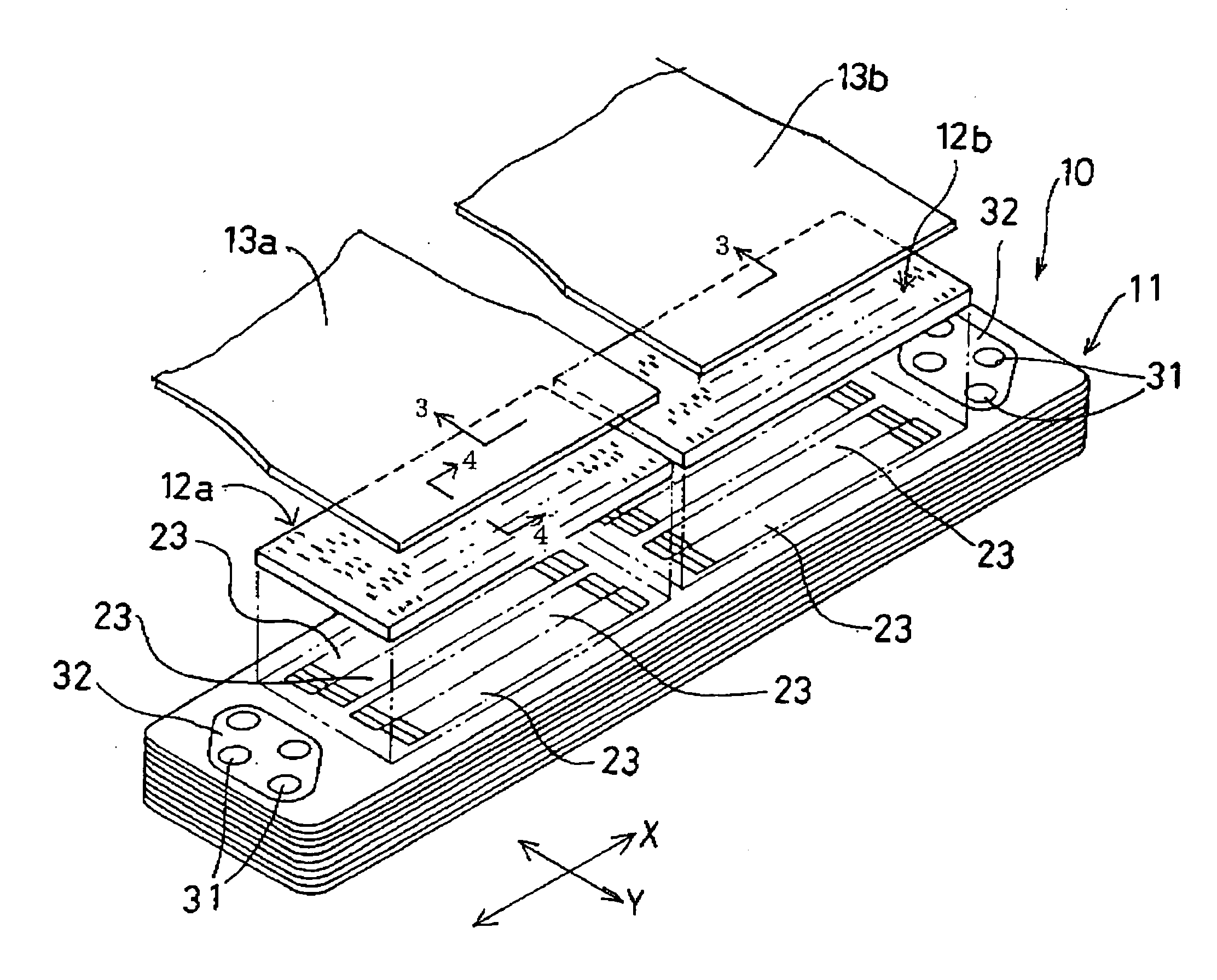
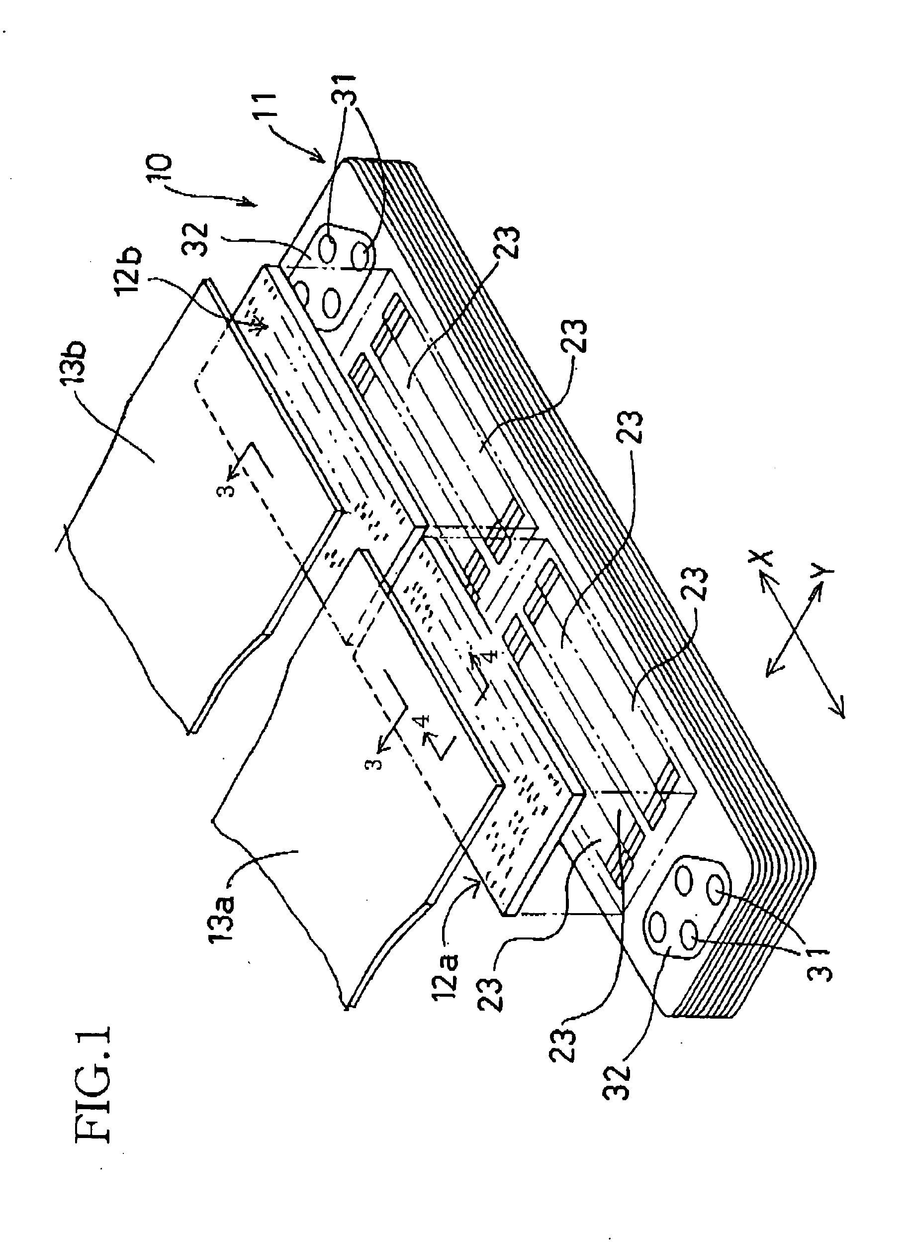
[0071] First, a piezoelectric-type ink jet printer head 10 to which the present invention is applied is briefly described by reference to FIGS. 1 through 4. In FIG. 1, the piezoelectric ink jet printer head 10 includes, in an order from its bottom to its top, a channel unit 11 constituted by a plurality of stacked metal sheets; two piezoelectric actuators 12a, 12b each of which is constituted by a plurality of stacked piezoelectric sheets; and two flexible flat cables 13a, 13b each as a cable member for connecting a corresponding one of the two piezoelectric actuators 12a, 12b to an external device, not shown. The channel unit 11, the piezoelectric actuators 12a, 12b, and the flexible flat cables 13a, 13b are stacked on each other, and are adhered to each other with an adhesive.

[0072] As shown in FIGS. 3 and 4, the channel unit 11 is constituted by nine thin sheet...

first modified embodiment

[0115]FIG. 7A shows the first embodiment shown in FIGS. 1 through 6. In this modified embodiment, each of the first and second bridge portions 53, 54 connected to each one of the sheet members 14 through 22 includes, as a portion thereof that is near to a corresponding one of the short-side and long-side end portions of the each sheet member 14 through 22, a weakened portion 61 which is formed, by, e.g., etching, to have a groove and accordingly a thickness smaller than that of the remaining portion of the each bridge portion 53, 54.

[0116] In the first modified embodiment shown in FIG. 7A, since shearing forces used to cut off the bridge portions 53, 54 are concentrated to the respective weakened portions 61 of the bridge portions 53, 54 that are low in strength, each of the sheet members 14 through 22 can be easily removed from the corresponding frame portion 52 and one or two adjacent sheet members 14 through 22 that is or are located adjacent the each sheet member. In addition, a...

second modified embodiment

[0117]FIG. 7B shows the present invention in which each of the first and second bridge portions 53, 54 includes a different weakened portion 61 having a recess. For example, in the case where a thickness of each of the bridge portions 53, 54 is considerably small, the each bridge portion 53, 54 including the weakened portion 61 can enjoy a sufficiently high strength while allowing each sheet member 14 through 22 to be easily removed from the corresponding frame portion 52 and one or two adjacent sheet members 14 through 22.


PUM


Abstract

A sheet-member stacked structure produced by a method including one or more of the following steps: stacking lead frames on each other, and stacking sheet members of one lead frame on sheet members of another or other lead frame or frames, each lead frame including a frame portion, the sheet members, first groups of bridge portions, and second groups of bridge portions each group of which connect two opposite sides of a corresponding one of the sheet members, to an inner peripheral portion of the frame portion and one of two opposite sides of its adjacent sheet member, or to respective one sides of its two adjacent sheet members; stacking sheet members on each other via an adhesive, a contact surface of one of each pair of adjacent sheet members having a relief groove formed along a location where the adhesive is applied, each of the stacked sheet members except for one of the two opposite, outermost sheet members having a relief hole communicating with the relief groove and formed through a thickness of the each sheet member, at least a portion of the relief hole of the other outermost sheet member having a cross-section area greater than a cross-section area of the relief hole of each of the other sheet members; and stacking sheet members on each other, the sheet members including a liquid-chamber sheet member formed of a rolled metal sheet and having liquid chambers arranged, separately from each other, in a direction perpendicular to a direction of rolling of the metal sheet.

Description

[0001] The present application is based on Japanese Patent Application No. 2003-193842 filed on Jul. 8, 2003, Patent Application No. 2003-200254 filed on Jul. 23, 2003, and Patent Application No. 2003-201674 filed on Jul. 25, 2003, the contents of which are incorporated herein by reference. BACKGROUND OF THE INVENTION [0002] 1. Field of the Invention [0003] The present invention relates to a sheet-member stacked structure; the present invention also relates to a lead frame which may be is used with one or more other lead frames to assemble a plurality of sheet members into a component of, e.g., an ink jet printer head or an electronic device; the present invention also relates to a sheet-member stacked and adhered structure in which a plurality of sheet members are stacked on, and adhered to, each other and which is employed by, e.g., an ink jet printer head or an electronic device; and the present invention also relates to an ink jet printer head and particularly to such a sheet-me...

Claims


Application Information

Patent Timeline
Patent Type & Authority Applications(United States)
IPC IPC(8): B41J2/14B41J2/16
CPCB41J2/14209B41J2/1609B41J2/1623B41J2/1626B41J2002/14419B41J2002/14217B41J2002/14225B41J2002/14306B41J2/1635
Inventor ITO, ATSUSHI
Owner BROTHER KOGYO KK
Why Eureka
Try Eureka