Optical information recording medium, optical information recording apparatus, information processing apparatus, optical information recording method, program and recording medium

Active Publication Date: 2005-02-24
RICOH KK
View PDF25 Cites 17 Cited by
  • Summary
  • Abstract
  • Description
  • Claims
  • Application Information

AI Technical Summary

Benefits of technology

According to the first aspect of the present invention, it is possible to provide an address information formation method capable of accessing an arbitrary position of an optical information recording medium even if recording data are not recorded thereon, and avoiding interference by address information with respect

Problems solved by technology

Japanese Laid-Open Patent Application No. 2000-293947, however, does not disclose a specific formation method for embedding address in an unrecorded optical disk.
Further, when the number of sectors S in the first recording layer is different in each optical disk (for example, when the storage capacity per layer is different in each optical dis

Method used


Image

  • Optical information recording medium, optical information recording apparatus, information processing apparatus, optical information recording method, program and recording medium
  • Optical information recording medium, optical information recording apparatus, information processing apparatus, optical information recording method, program and recording medium
  • Optical information recording medium, optical information recording apparatus, information processing apparatus, optical information recording method, program and recording medium

Examples


Embodiment Construction

A description is given below of each embodiment of the present invention.

It should be noted that, in the following description, symbols as follows are used. That is, in “12BDh”, for example, the symbol “h” represents hexadecimal form. Thus, in this example, a hexadecimal numeric value “12BD” is represented. In addition, in “0010b”, the symbol “b” represents binary form. Thus, in this example, a binary numeric value “0010” is represented. Further, in “1234d”, the symbol “d” represents decimal form. Thus, in this example, a decimal numeric value “1234” is represented. A symbol “*” represents multiplication, and a symbol “ / ” represents division.

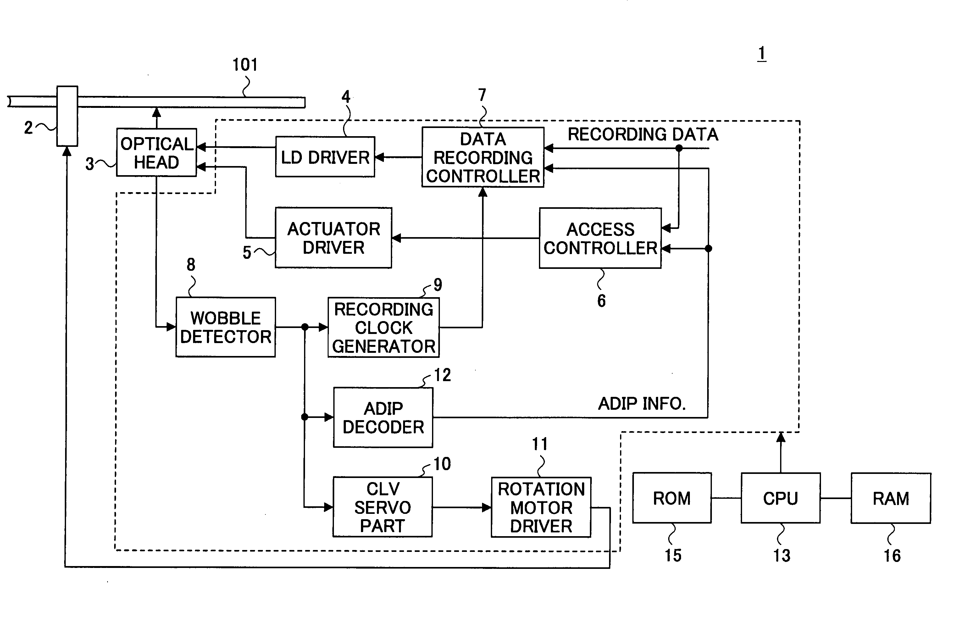
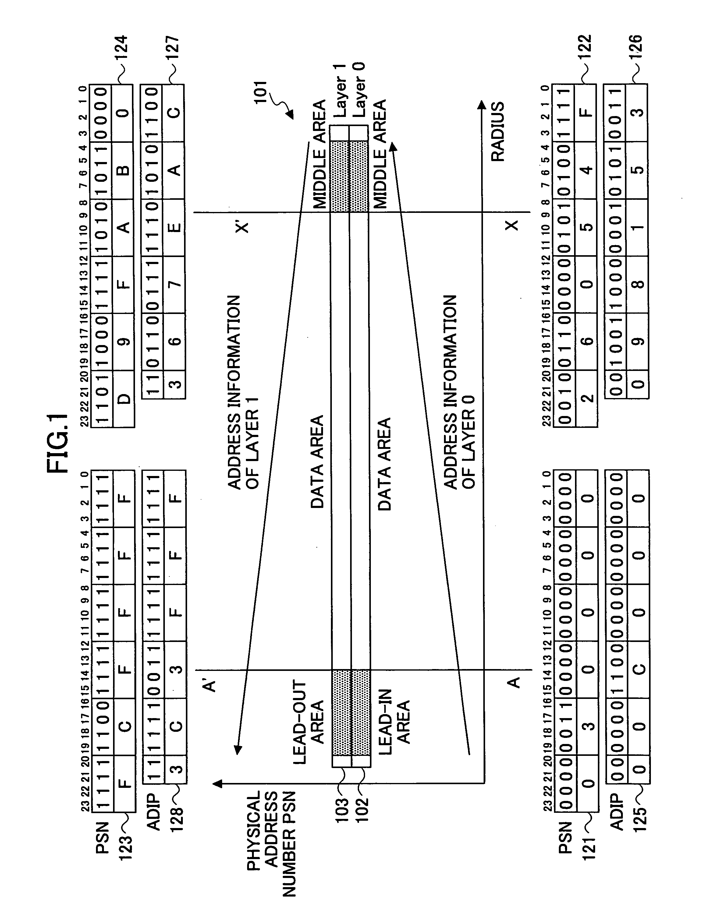
FIG. 1 is a diagram for explaining the structure of an optical disk 101 according to one embodiment of the present invention. The optical disk 101 is an optical information recording medium according to one embodiment of the present invention, and this optical disk is a DVD (Digital Versatile Disc) having two recording layers and allowing data...


PUM


Abstract

An optical disk 101 includes a plurality of recording layers 102 and 103 and allows recording of information on each of the recording layers 102 and 103. A spiral guide groove having wobbles meandering in radial directions of the optical disk 101 is formed on each of the recording layers 102 and 103. Recording data can be recorded on or between the guide grooves. ADIP, which is address information embedded by wobble modulation of the guide groove, is recorded. The address information indicates positional information with respect to a radial direction of the recording layer 102 or 103 of the optical disk 101 on which the wobbles of the guide groove are formed.

Description

BACKGROUND OF THE INVENTION 1. Field of the Invention The present invention relates to: an optical information recording medium having a plurality of recording layers and allowing recording of information on each of the recording layers; an optical information recording apparatus and an optical information recording method that perform data recording on the optical information recording medium; an information processing apparatus provided with the optical information recording apparatus; a program causing a computer that controls the optical information recording apparatus to perform data recording on the optical information recording medium; and a recording medium recording the program thereon. 2. Description of the Related Art Optical disks such as DVDs can increase the total storage capacity by providing two or more recording layers. In such optical disks, recording and reproducing can be performed by accessing from a single side thereof and adjusting the focus of an optical ...

Claims


Application Information

Patent Timeline
IPC IPC(8): G11B7/0045G11B7/005G11B7/007G11B7/24038G11B7/24082G11B20/12G11B27/19G11B27/24
CPCG11B7/24082G11B20/1217G11B27/24G11B2020/1227G11B2020/1239G11B2220/2562G11B2220/218G11B2220/235G11B2220/2525G11B2220/2537G11B2220/2545G11B2020/1267
Inventor SUZUKI, HARUYUKI
Owner RICOH KK
Why Eureka
Try Eureka