
Providing wireless data services via public telephones

Inactive Publication Date: 2005-02-24
SONERA
View PDF7 Cites 4 Cited by
  • Summary
  • Abstract
  • Description
  • Claims
  • Application Information

AI Technical Summary

Benefits of technology

[0011] The invention relies on public telephones and a part of their existing wiring to convey data services to mobile subscribers. Unlike the Sato et al. technique, the present invention is based on the idea of providing public telephones with packet-switched connections. The use of packet-switched connections has several advantages. For example, each user can be debited on the basis of the amount of transferred data, or the purchased right to transfer a given amount of data. The ability to purchase a right to transfer a given amount of data makes it possible to pay for the connection in advance, whereby the connection can be paid for by means of a short message, for example, or by inserting coins to the public telephone. Alternatively, a telephone card (a smart card) can be inserted into the card reader of the public telephone, the card is debited, after which the card can be withdrawn and another user may use the same public telephone for voice or data connections, while the first user is using their data connection. This is a definite advantage over the prior art public telephones in which a smart card must be inserted in a card slot for the entire duration of a call.

Problems solved by technology

A general problem with most wireless data connection techniques is that subscribers are only supported within their home network, that is, within the coverage area of their home network operator.
This analogy is not perfect, however, because the typical use of data connections is very different from how public telephones are typically used.
Even if a user would be willing to pay for a long data connection, it is socially unacceptable to reserve public telephones for extended periods of time.
In other words, a specific problem of the Sato et al. technique is that the billing remains an open question.

Method used


Image

  • Providing wireless data services via public telephones
  • Providing wireless data services via public telephones
  • Providing wireless data services via public telephones

Examples


Embodiment Construction

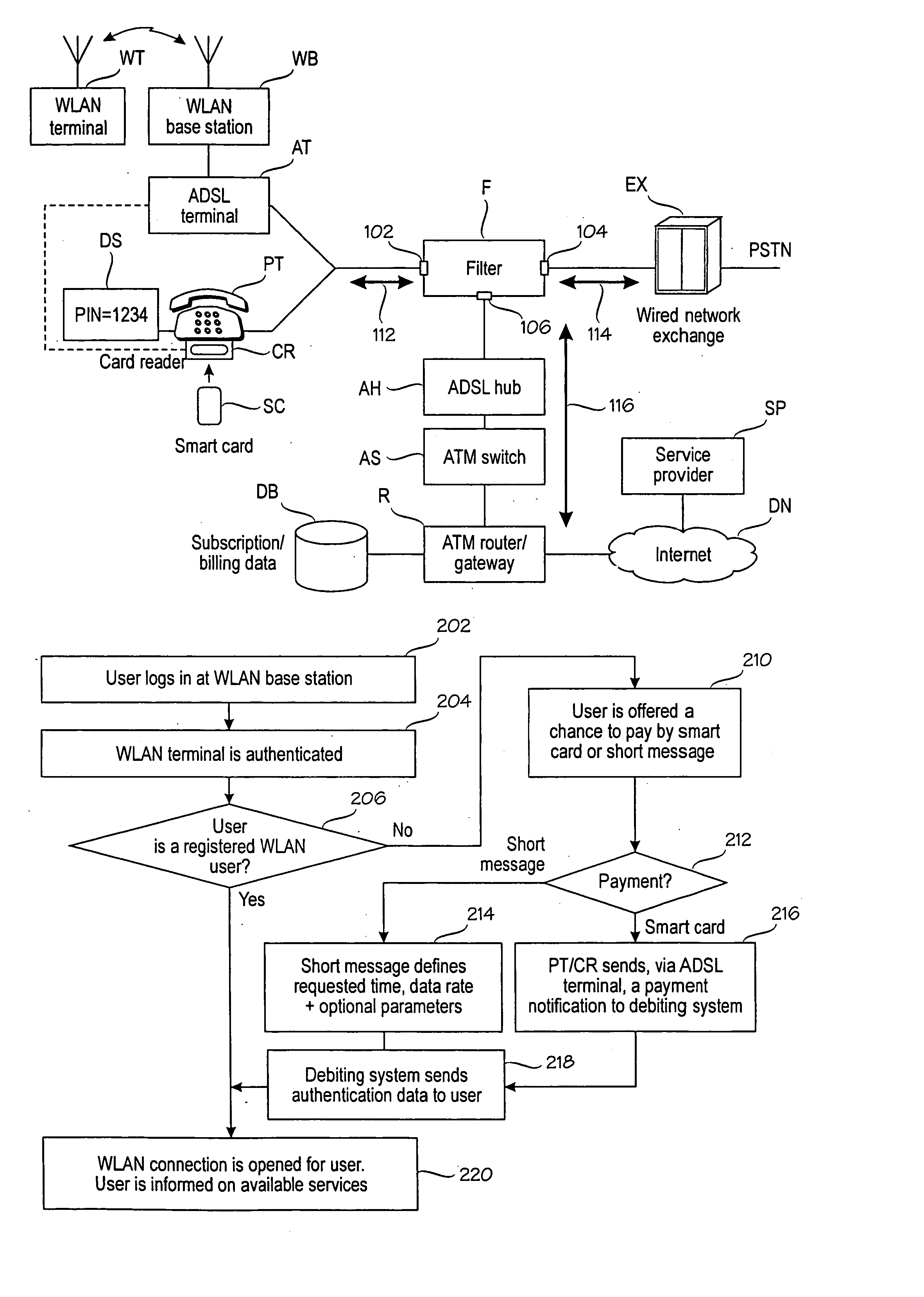
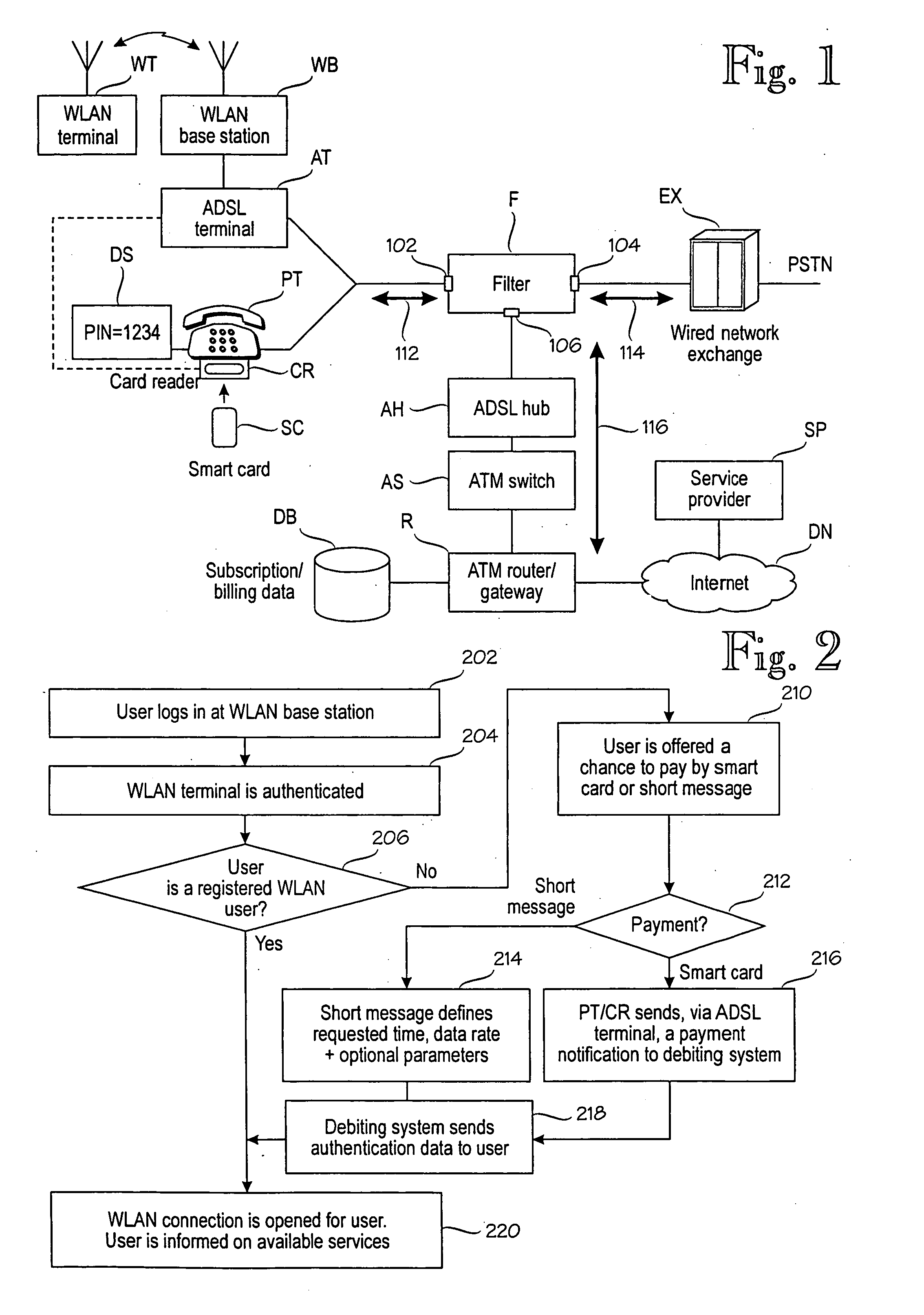
[0016]FIG. 1 is a block diagram illustrating an embodiment of the invention. As is well known, a public telephone PT is normally connected to a wired network exchange EX. Voice calls are conveyed via a circuit-switched data path 114 between the public telephone PT and the exchange EX. In this example, the public telephone PT comprises (or is connected with) means for accepting payment, such as a card reader CR for accepting smart cards SC. Alternatively, cash payment can be used. In addition, the public telephone PT comprises a display DS. The display is normally used for showing the available call time or tariff to a user, but in some embodiments of this invention, the display is also used to display authentication data to wireless terminal users. If the telephone PT does not have a display, authentication data can be indicated orally, by means of a voice synthesizer (not shown separately).

[0017] To support wireless data services, wireless communication means are connected in para...


PUM


Abstract

An arrangement for providing a wireless data service from a service provider (SP) to a wireless terminal (WT). The arrangement comprises a public telephone (PT). In order to provide packet-switched connection, which can be shared among multiple terminals, the arrangement comprises a filter (F) that directs voice traffic to a circuit-switched data path (114) between an exchange (EX) and the filter, and data services to a packet-switched data path (116) between the a network (DN) and the filter. Voice traffic and data services share a common data path (112) between the public telephone (PT) and the filter. There are wireless communication means, such as a WLAN base station (WB) and an ADSL terminal (AT), operationally coupled to the filter, for conveying the wireless data service to the wireless terminal (WT). Debiting means (R, DB) control debiting of the wireless terminal for the use of the wireless data service.

Description

[0001] This application is a Continuation of International Application PCT / FI02 / 00867 filed Nov. 7, 2002 which designated the U.S. and was published under PCT Article 21 (2) in English.BACKGROUND OF THE INVENTION [0002] The invention relates to methods and equipment for offering wireless data services to wireless terminals, whose subscribers are outside of their home networks or who do not have a home network. [0003] Wireless networks have been proposed as a solution to improve the mobility of data processing equipment. For example, WLAN (Wireless Local Area Networks) networks can be used to establish a data connection to a portable or handheld computer. [0004] A general problem with most wireless data connection techniques is that subscribers are only supported within their home network, that is, within the coverage area of their home network operator. A partial solution to this problem is disclosed in EP 0449 119 B1 by Risaburo Sato et al. (“Sato”). Sato discloses the use of publi...

Claims


Application Information

Patent Timeline
IPC IPC(8): H04L12/28H04L12/54H04M15/00H04M17/00H04M17/02H04W4/24H04W40/02H04W76/02H04W84/12H04W88/08
CPCH04L12/2856H04W88/08H04M15/00H04M15/30H04M15/51H04M15/55H04M15/67H04M15/68H04M15/8016H04M15/83H04M15/854H04M17/00H04M17/02H04M2215/0196H04M2215/2026H04M2215/22H04M2215/32H04M2215/44H04M2215/48H04M2215/54H04M2215/7414H04M2215/8166H04M2215/82H04M2215/92H04W4/24H04W40/02H04W76/026H04W84/12H04L12/5692H04W76/16
Inventor KAMARI, JUKKASUTINEN, PASIPATYNEN, MARKKUTAPIOLA, JUHANIKOSKELAINEN, TIMO
Owner SONERA
Learn More