Light amount adjusting apparatus, optical equipment, optical filter and image-taking apparatus

a technology of light amount and adjustment apparatus, which is applied in the direction of exposure control, camera focusing arrangement, printers, etc., can solve the problems of loss of three-dimensional impression and image depth, and inability to adjust the light amoun

Active Publication Date: 2005-02-24
CANON KK
View PDF4 Cites 36 Cited by
  • Summary
  • Abstract
  • Description
  • Claims
  • Application Information

AI Technical Summary

Benefits of technology

[0024] A light amount adjusting apparatus according to one aspect of the present invention comprises an optical filter whose optical density increases continuously from its center toward its periphery, a first actuator serving as a driving source of the optical filter, and a control circuit operating the optical filter with respect to an aperture formed in the light amount adjusting apparatus by controlling the driving of the first actuator.

Problems solved by technology

However, the following problems occur when the optical characteristics of the apodization filter are inappropriate:
(B) When a transmission rate at an outer periphery of a filter is too small, then a diameter of blurred images becomes small, and a three-dimensional impression and an impression of depth of an image are lost.
(C) When a shape of a transmission rate distribution is inappropriate, then the contours of blurred images become unnatural.
(D) When the average transmission rate of an overall effective filter portion is too small, then a transmitted light quantity is reduced, extending an exposure time and increasing an effect of camera shake.
(1) With a cemented glass filter as disclosed in U.S. Pat. No. 3,843,235 and on pages 74-77 of the April 1999 issue of “SHASHIN KOGYO,” that is, with the apodization filter made by cementing together the planar-concave lens made of light-absorbing glass and the convex-planar lens made of transparent glass, a shape of the transmission rate distribution is limited substantially to the Gauss distribution (also referred to as a “normal distribution” in stochastic theory), and it is difficult to obtain characteristics that provide a well-balanced solution of the problems (A) to (D) described above.
H10 (1998)-268382, the camera operator must change the apodization filters manually, so that its handling properties are poor and there is the risk of missing out on good photo opportunities.
(2) With the apodization filter disclosed in U.S. Pat. No. 3,843,235, which is made by cementing together the planar-concave lens made of light-absorbing glass and the convex-planar lens made of transparent glass, the degree of freedom for the design of the transmission rate distribution is low, and moreover there is the problem that the image-forming optical system tends to become large, because a thickness of the filter has to be made large.
(3) Not only the above-described apodization filter made by cementing together the planar-concave lens made of light-absorbing glass and the convex-planar lens made of transparent glass, but also apodization filters made by forming the photosensitive resin or the vapor-deposited film on the transparent base, which can be expected to be made thinner and lighter in the future, are expensive in view of their workability and the facilities that are required to manufacture them.
On the other hand, in image-taking apparatuses for capturing still pictures or moving images by using an image-pickup system such as a silver-halide film or an image-pickup means such as a CCD, there are deficiencies with regard to not only the light amount adjusting function but also the focus adjustment function when trying to obtain high-quality images.
However, in the related technologies, there is no disclosure regarding a method for focus adjustment when using an apodization filter.
However, in focus defection devices employing phase difference detection method, when a transmission rate is changed continuously at the pupil position of the image-taking lens due to an apodization filter, then an illumination distribution of an object for focus detection which is projected onto an AF sensor is not uniform, so that focus detection discrepancies occur.

Method used


Image

  • Light amount adjusting apparatus, optical equipment, optical filter and image-taking apparatus
  • Light amount adjusting apparatus, optical equipment, optical filter and image-taking apparatus
  • Light amount adjusting apparatus, optical equipment, optical filter and image-taking apparatus

Examples


embodiment 1

[0095] FIGS. 1 to 7 illustrate Embodiment 1 of the present invention.

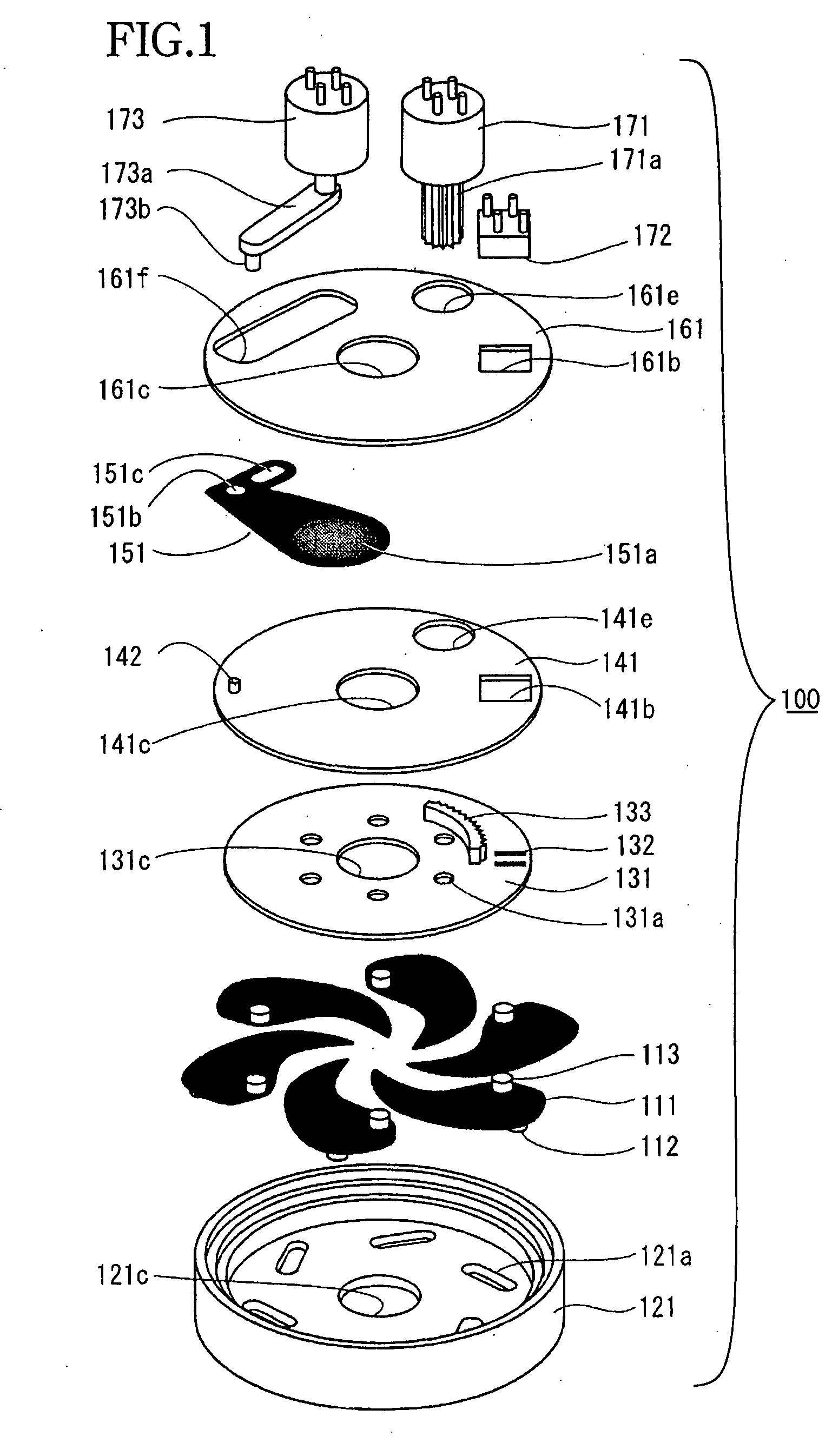
[0096]FIG. 1 is an exploded perspective view showing essential parts of a light amount adjusting apparatus 100 incorporating an apodization filter according to the present invention. In FIG. 1, reference numeral 111 denotes diaphragm blades having a property of blocking light across their entire region. Driven pins 112 and 113 are arranged upright on the lower and the upper surface of the diaphragm blades 111. Six diaphragm blades 111 of the same shape are used, forming a diaphragm aperture. It should be noted that the larger the number of diaphragm blades 111 is, the closer the shape of the aperture becomes to being circular when the diaphragm blades 111 are constricted, improving the naturalness of the blurred image and easing the diffraction phenomena due to the vertices of the polygonal aperture, but a larger number of blades also incurs greater manufacturing costs. Consequently, in the present diaphragm mecha...

embodiment 2

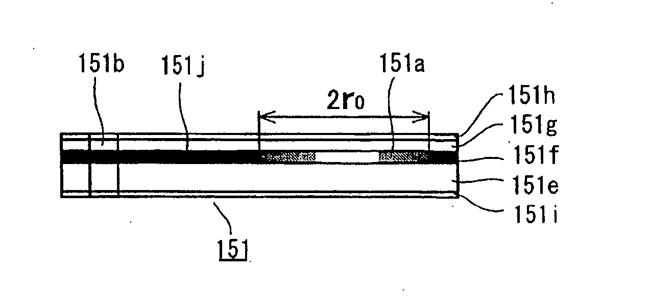
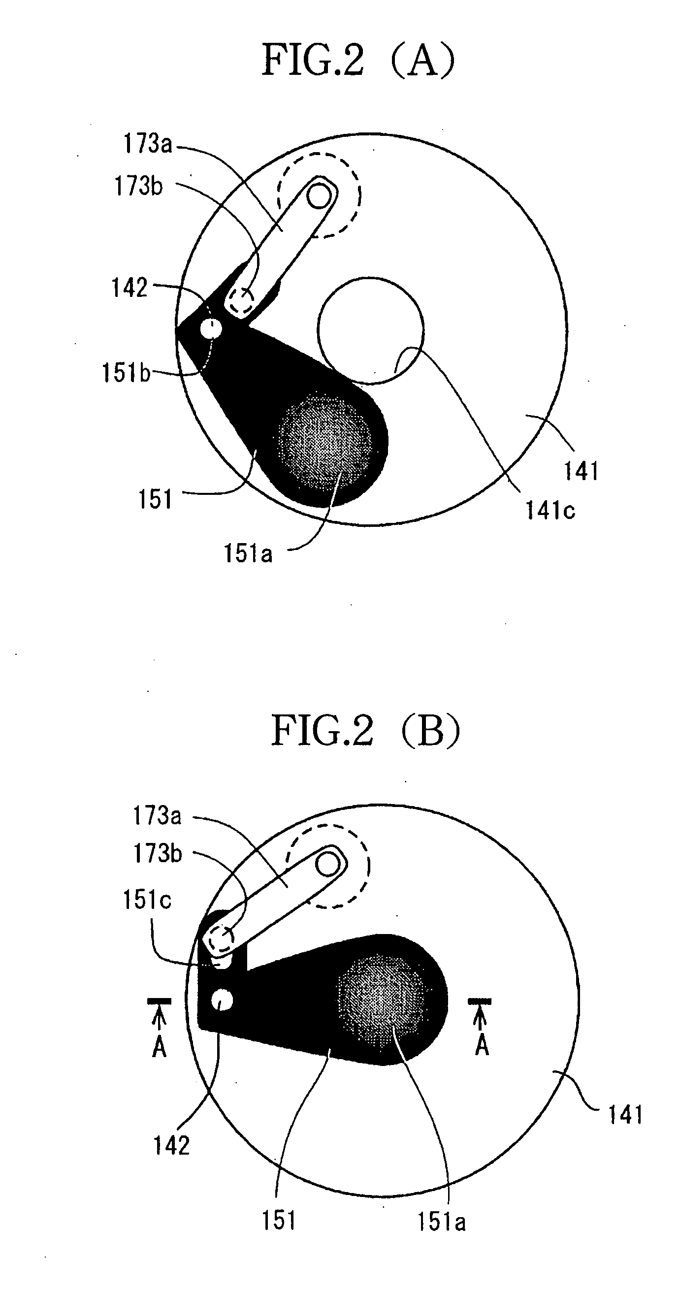
[0147] The apodization filter 151 used in Embodiment 1 has only one filter portion in which the transmission rate distribution decreases linearly from the center to the periphery, and the actuator only advances or retracts the filter with respect to the light flux transmitted through the light-flux transmission aperture, whereas Embodiment 2 explained below is an example in which a plurality of apodization filters are arranged on one filter substrate, and the most appropriate effective filter portion can be selected in accordance with the image-taking intentions.

[0148]FIG. 8 is an exploded perspective view illustrating a structure of a light amount adjusting apparatus 200 according to Embodiment 2 of the present invention, and corresponds to FIG. 1 in Embodiment 1.

[0149] In FIG. 8, reference numeral 211 denotes diaphragm blades having a property of blocking light across their entire region. Driven pins 212 and 213 are arranged upright on a lower and an upper surface of the diaphra...

embodiment 3

[0179] FIGS. 14 to 25 illustrate Embodiment 3 of the present invention.

[0180]FIG. 14 is an exploded perspective view showing essential parts of a light amount adjusting apparatus 100 incorporating an apodization filter according to the present invention. In FIG. 14, reference numeral 111 denotes diaphragm blades having a property of blocking light across their entire region. Driven pins 112 and 113 are arranged upright on a lower and an upper surface of the diaphragm blades 111. Six diaphragm blades 111 of the same shape are used, forming a diaphragm aperture. It should be noted that a larger the number of diaphragm blades 111 is, the closer a shape of an aperture becomes to being circular when the diaphragm blades 111 are constricted, improving a naturalness of a blurred image and easing a diffraction phenomenon due to vertices of the polygonal aperture, but a larger number of blades also incurs greater manufacturing costs. Consequently, in the present diaphragm mechanism, it is p...


PUM


Abstract

An optical filter is disclosed which adjusts the contours of blurred images and maintains the size of blurred images. The optical filter includes a substrate being substantially transparent and a first layer whose optical density changes continuously, formed on the substrate. A transmission rate of the first layer decreases substantially linearly from a center toward a periphery of the optical filter, and the transmission rate distribution is symmetric with respect to the center.

Description

BACKGROUND OF THE INVENTION [0001] 1. Field of the Invention [0002] The present invention relates to an optical filter for obtaining a favorably out-of-focused image when taking photographs, as well as to a light amount adjusting apparatus and an image-taking apparatus to which such an optical filter is mounted. [0003] 2. Description of Related Art [0004] In the past, technology has been disclosed related to optical filters for improving out-of-focused image, so-called blurred images which are not in focus and to cameras incorporating such optical filters. An example of such filters are apodization filters. Apodization filters are devised so that their transmission rate decreases with increasing distance from a center of the optical axis in directions perpendicular to the optical axis, and when such a filter is used, then the contours in a blurred image become smooth, and cross-eyed bokeh and ring bokeh are eased. Accordingly, in scenes in which the focus depth is small, such as whe...

Claims


Application Information

Patent Timeline
Patent Type & Authority Applications(United States)
IPC IPC(8): G02B5/22G02B27/58
CPCG02B27/58G02B5/22
Inventor ONUKI, ICHIRONAMAZUE, ERIKOKASHIWAZAKI, AKIOKANOME, OSAMUWATANABE, KOHEI
Owner CANON KK
Why Eureka
Try Eureka