Drainage and irrigation approach and structure as well as its implementation

a technology of irrigation and water supply, applied in the direction of paving gutters/kerbs, roads, agriculture, etc., can solve the problems of affecting the water supply of the road, so as to promote water and soil conservation and improve the environmental conditions.

Inactive Publication Date: 2005-02-24
FU CHANGBIAO
View PDF0 Cites 27 Cited by
  • Summary
  • Abstract
  • Description
  • Claims
  • Application Information

AI Technical Summary

Benefits of technology

[0008] The purpose of this Invention is to provide a drainage and irrigation approach and structure, which, in the event of rainfalls and road cleaning, may function simultaneously in two ways: retaining dirt and debris in the green belts and seeded strips to avoid drainage pipeline blockage, downstream water body contamination, and soil loss on the one hand, and properly allocating water consumption and making better use of external water resources in the green belts and seeded strips to improve the environmental conditions on the roads and green belts as well as seeded strips, promote the water and soil conservation in the green belts and planting area, and cultivate the natural conditions for plant growth.

Problems solved by technology

Sands and other debris carried by the water are stopped and stranded between the curb barrier stones and the pavement.
Such maintenance work requires a lot of labor and expenses.
In a heavy rainfall, the vegetation may easily be damaged, the soil be washed away, and the water resources be wasted.
Sludge and other debris carried by the water may contaminate and clog the pipes.
Debris removal will require a lot of labor and expenses.
In addition, the water resources are wasted.
The conventional technology as evidenced in the examples presented in the previous paragraphs has created a lot of problems in road debris removing, which has been costly and labor intensive.
Road maintenance often generates a lot of dust, thus continually causing pollution.
In addition, rainfalls or irrigation of the green belts and seeded strips along the roads cause soil loss, underground pipe clogging and contaminating, and contamination of downstream water resources.
We are confronted not only with the issue of soil and water loss, but also with the risk of on-going contamination.

Method used


Image

  • Drainage and irrigation approach and structure as well as its implementation
  • Drainage and irrigation approach and structure as well as its implementation
  • Drainage and irrigation approach and structure as well as its implementation

Examples


Embodiment Construction

[0046] The application samples presented in the following paragraphs are intended to illustrate in detail the implementation and benefits of this Invention so that readers may see the creativity embodied in this Invention. The samples should be studied together with the drawings.

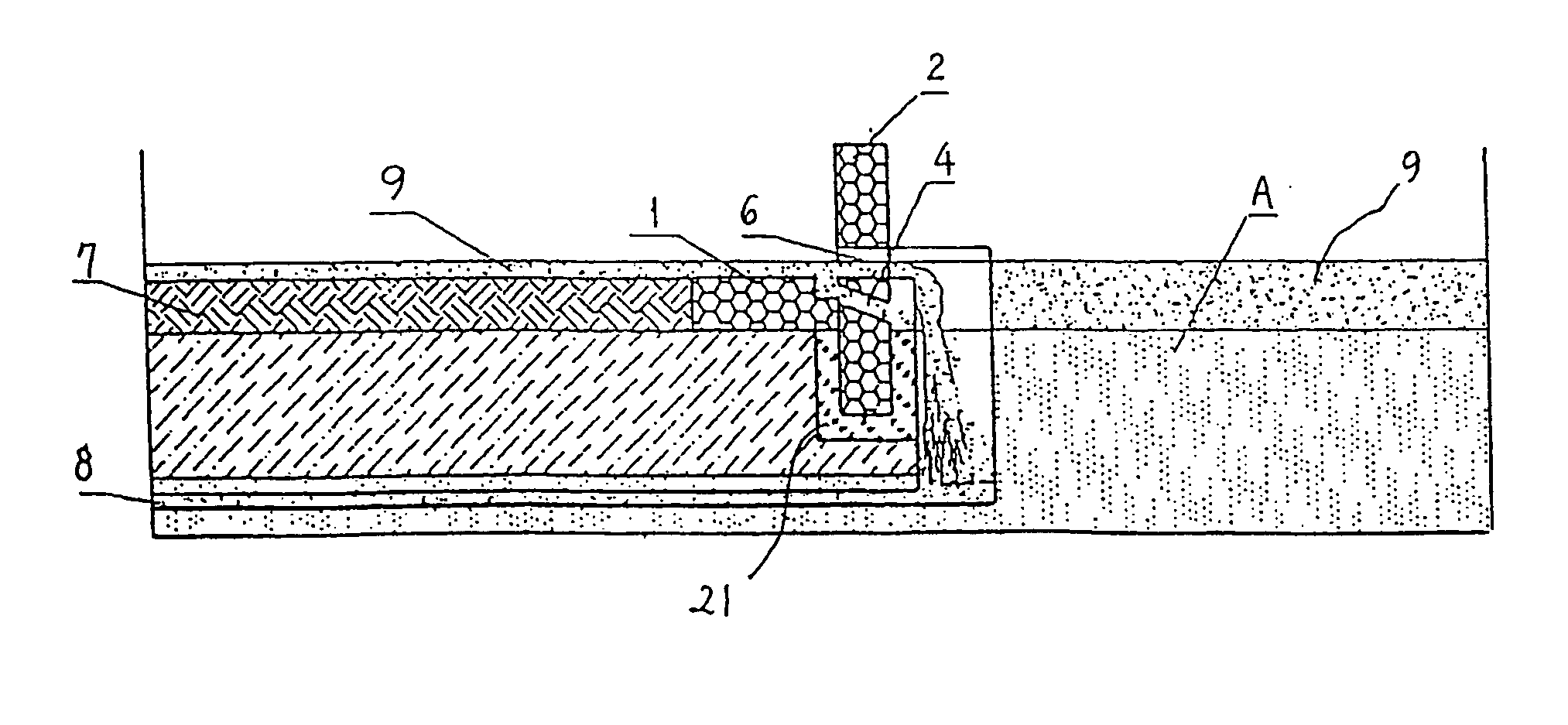
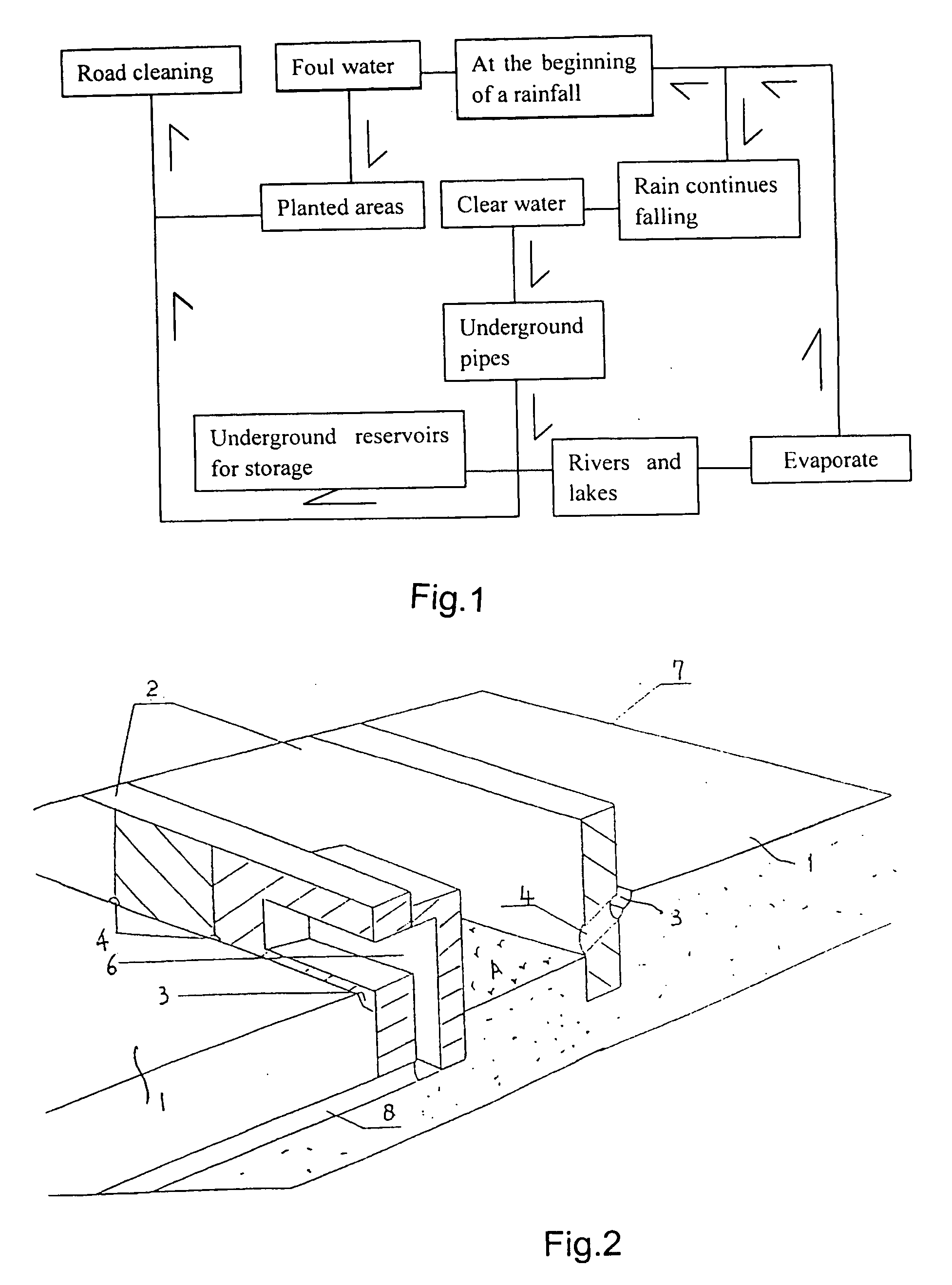
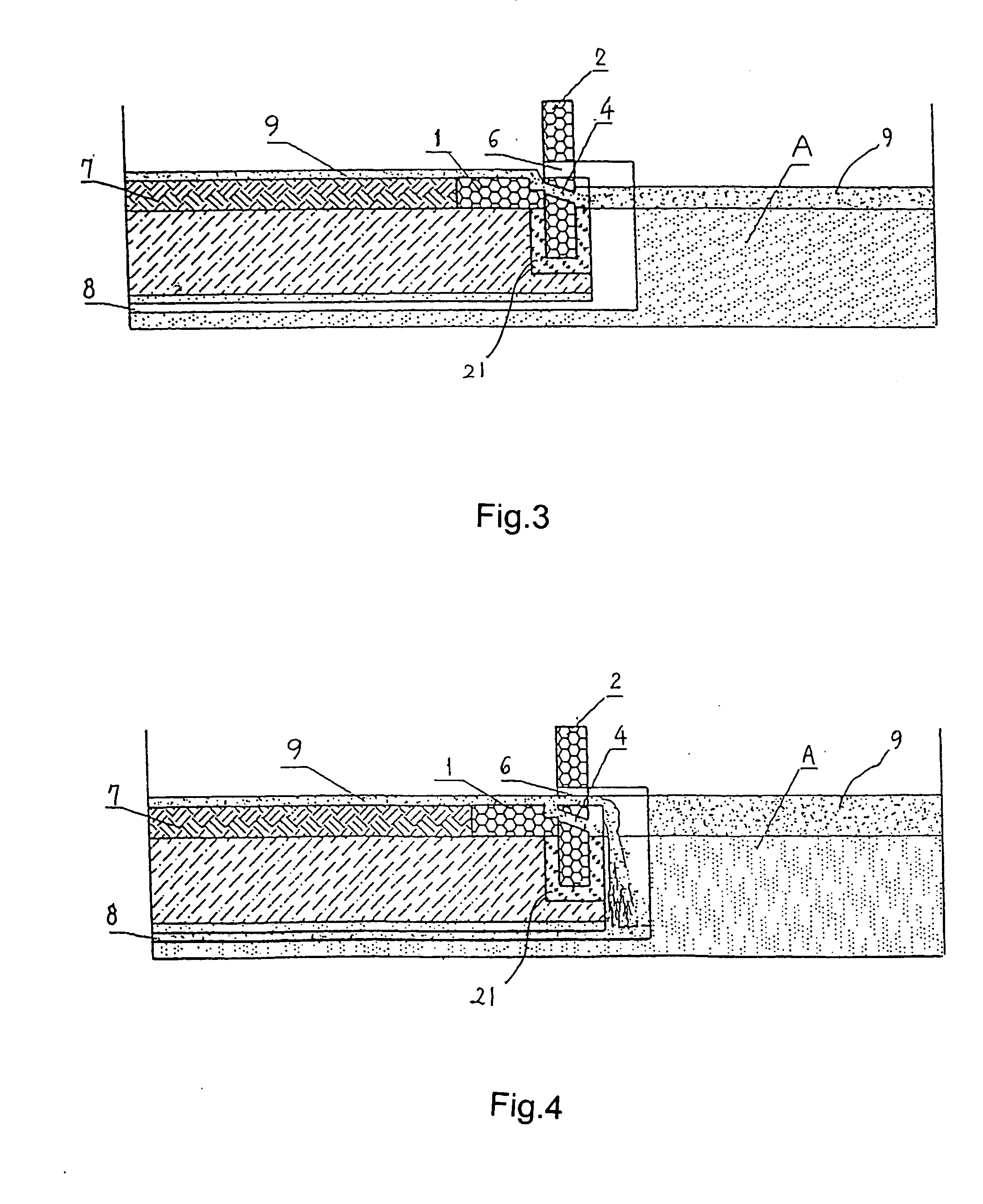
[0047] See FIG. 1, which is an operation flow chart of this Invention. This Invention involves a drainage and irrigation approach suitable for both rainwater and road cleaning water. The said approach consists of two stages: the initial stage of irrigating green belts and seeded strips and the later stage of rainwater drainage. In the initial irrigation stage, rainwater at the beginning of a rainfall or foul water in the event of road cleaning with debris flow through drainage holes in the drainage and irrigation structure onto the planted areas, thereby providing the nutrients and water necessary for plant growth. If the rain continues falling and the rainwater rises to a certain level, it flows through th...


PUM


Abstract

This Invention relates to a drainage and irrigation approach, which primarily includes the initial stage of green belt irrigation and the later stage of rainwater drainage. The drainage and irrigation structures employed in this approach consist of curb stones, edge stones, border stones, and boundary stones, which may have combinations of drainage troughs [3], rainwater ports [6] and drainage holes [4], or drainage troughs [3] and rainwater ports [6], or drainage troughs [3] and drainage holes [4]. Depending on the conditions of planted areas, the drainage and irrigation structures discussed above may be deployed along roads, landscaping on top of architectural structures, planted areas, seeded strips or barren hill slopes.

Description

TECHNICAL AREA [0001] This Invention relates to a drainage and irrigation approach and structure as well as its implementation. In particular, it relates to a drainage and irrigation approach and structure as well as its implementation in connection with roads, landscaping on top of architectural structures, green belts, planted borders, and barren hill slopes. BACKGROUND TECHNOLOGY [0002] Roads, drainage pipeline networks, and landscaping are important urban infrastructures, which have a direct impact on the quality of the urban environment. The conventional road curb generally consists of curb barrier stones and flat curb stones. The flat curb stones are laid horizontally along one side or both sides of the road, with their upper surface flush with the road pavement. The curb barrier stones are laid perpendicularly to and tightly against the flat curb stones along the outer edge of the road, with their upper surface higher than the road pavement. To facilitate the drainage of rain...

Claims


Application Information

Patent Timeline
Patent Type & Authority Applications(United States)
IPC IPC(8): E03F5/046
CPCE03F5/046Y02A30/60
Inventor FU, CHANGBIAO
Owner FU CHANGBIAO
Why Eureka
Try Eureka