Catheter assembly

a catheter and assembly technology, applied in the field of catheter assembly, can solve the problems of difficult and expensive storage, transportation and handling, assembly expensive and harmful to the environment, and the above-described problem of bulkiness, etc., and achieve the effect of low friction surface character, effective rupture control, and cost effectiv

Inactive Publication Date: 2005-02-24
ASTRA TECH SE
View PDF12 Cites 78 Cited by
  • Summary
  • Abstract
  • Description
  • Claims
  • Application Information

AI Technical Summary

Benefits of technology

[0035] According to this method, similar advantages as discussed above are achieved.
[0036] According to another aspect of the invention, it relates to a catheter assembly comprising: a catheter having on at least part of its surface a hydrophilic surface layer intended to produce a low-friction surface character of the catheter by treatment with a wetting fluid prior to use of the catheter; a catheter receptacle forming a cavity for accommodation of at least part of the catheter; and a compartment accommodating said wetting fluid, wherein said compartment forms an integrated part of the receptacle, but being separated from said cavity, wherein the separation between the wetting fluid compartment and the cavity accommodating the catheter provides a rupturable sealed closure. Further, said closure is provided with at least one point of weakness, in order for an induced rupture to occur in a predetermined position, thereby enabling fluid communication between the compartment and the cavity housing the catheter.
[0037] In accordance with this embodiment of the invention, a rupture of the fluid compartment could be effectively controlled, in order for it to occur in a predetermined position. Hereby, it could be avoided that the compartment, upon application of pressure or the like, is ruptured in a random position, which could lead to leakage of the fluid, insufficient wetting of the hydrophilic surface, etc. Instead, the rupture will always occur in the most effective position, leading to an effective wetting of the catheter surface.
[0038] Preferably, the closure is formed by a rupturable joint between the compartments, and most preferably the joint is a welded joint with a welding width variation, or a welding strength variation, thus providing the at least one point of weakness. Alternatively, the joint could be arranged in a non-linear arrangement, thus providing the at least one point of weakness. In this case, the joint could be arranged with at least one knee directed towards the wetting fluid compartment. The knee could e.g. have an angled peak portion directed towards the wetting fluid compartment, with an obtuse or acute angle. However, the knee may alternatively have an curved peak portion directed towards the wetting fluid compartment. Hereby, effective rupture control may be achieved, and at the same time a very cost effective and easily producible joint is provided.

Problems solved by technology

However, a problem with such catheter assemblies are that they are bulky, making them difficult and expensive to store, transport and handle.
Further, a lot of packaging and wrapping material is required, making the assemblies expensive and harmful to the environment.
However, unfortunately the inclusion of such a wetting fluid container makes the above-described problem with bulkiness, etc, even more severe.
However, in such a catheter, a relatively large amount of wetting fluid is required to fill the receptacle to a certain degree and to ensure that an adequate wetting of the catheter is maintained. accordingly, even this type of catheter assembly suffers from the bulkiness discussed above, and is further relatively heavy.
Further, a problem with this type of catheter assemblies are that the catheter becomes wet and slippery, which makes it uncomfortable and difficult to handle.
There is further a problem with known catheter assemblies that the catheter must normally be removed from the receptacle or package before it could be connected to other devices, such as drainage tubes, urine bags, etc.
Hereby, the handling of the catheter becomes more difficult, since more work has to be done by the person responsible for the catheterization, and especially during the stressed situation when the catheter is exposed to the environment, instead of in advance, or even as a step during the production process.
Further, the time period when the catheter is exposed, and accordingly vulnerable to contamination and the like, is prolonged, which increases the risk for the patient.

Method used


Image

  • Catheter assembly
  • Catheter assembly
  • Catheter assembly

Examples


first embodiment

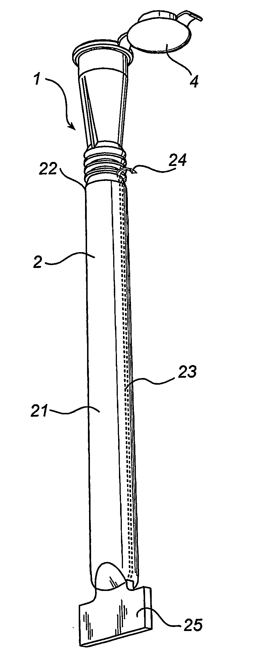
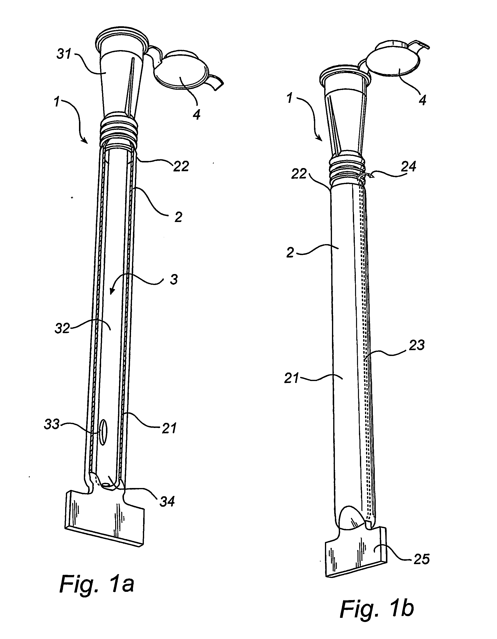
[0055] Referring first to FIG. 1, a catheter assembly 1 according to the invention comprises a wetting receptacle or bag 2, preferably of a transparent flexible plastics material. The receptacle 2 has a downwardly extending elongate pocket 21 at the forward end and an opening end 22.

[0056] The catheter assembly 1 further comprises a catheter, and preferably a hydrophilic urinary catheter 3, having a preferably flared rearward portion 31, an elongate shaft or tube 32 projecting forwardly from the rearward portion 31 and an open-ended lumen (not shown) which extends from the rear end of the rearward portion 31 to a drainage aperture 33 in the rounded tip 34. The rearward portion 31 could function as a connector of the catheter 3, being connectable to other devices, such as a urine collection bag, a drainage tube or the like. At least a part of the elongate tube 32 forms an insertable length to be inserted through a body opening of the user, such as the urethra in case of a urinary cat...

fifth embodiment

[0076] With reference to FIG. 5, the catheter assembly will now be discussed. In this embodiment, the catheter assembly 510 comprises a wetting receptacle or bag 520, preferably of a transparent flexible plastics material. The receptacle 520 has a downwardly extending elongate pocket 521 at the forward end and an opening end 522 (see FIG. 5b).

[0077] As in the previously discussed embodiments, the catheter assembly 510 further comprises a catheter, and preferably a hydrophilic urinary catheter 530. However, in this case a different type of connector 531 is used, with a different type of connection interface for connection to other devices, such as a urine collection bag a drainage tube or the like.

[0078] The catheter receptacle 520 is adapted for accommodation of the catheter tube in the elongate pocket 521, and the opening of the opening end 522 is connected to and closed by the connector or rearward end 531 of the catheter. Hereby, the receptacle encloses at least the insertable l...

sixth embodiment

[0087] With reference to FIG. 6, the catheter assembly will now be discussed. In this embodiment, the catheter assembly 610 comprises a wetting receptacle or bag 620, preferably of a transparent flexible plastics material. The receptacle 620 has a downwardly extending elongate pocket 621 at the forward end and an opening part 622 with an opening.

[0088] As in the previously discussed embodiments, the catheter assembly further comprises a catheter, and preferably a hydrophilic urinary catheter 630, with a connection interface for connection to other devices, such as a urine collection bag a drainage tube or the like. The catheter receptacle 620 is adapted for accommodation of the catheter tube in the elongate pocket 621, and the opening of the opening part 622 is connected to and closed by the connector 631 or rearward end of the catheter. Hereby, the receptacle encloses at least the insertable length of the catheter, but leaves at least part of the catheter outside the receptacle, sa...


PUM

PropertyMeasurementUnit
hydrophilicaaaaaaaaaa
frictionaaaaaaaaaa
wettingaaaaaaaaaa

Abstract

A catheter assembly is provided comprising a catheter (3;530;630;730) including a catheter tube (32) and a connector (31;531) arranged in one end of the catheter tube. The catheter is preferably a urinary, hydrophilic catheter. Further, the assembly comprises a catheter receptacle (2;520;620;720) for accommodation of at least the catheter tube, wherein the receptacle is provided with an opening (22;622;722), said opening being connected to and closed by the connector (31;531) of the catheter. A method for producing such a catheter assembly is also provided.

Description

FIELD OF THE INVENTION [0001] The present invention relates to a catheter assembly comprising a catheter and a receptacle for accommodation of at least part of the catheter. The invention further relates to a method for producing such a catheter assembly. BACKGROUND OF THE INVENTION [0002] Catheters find their use in many different medical applications, such as urinary catheters for bladder drainage. Catheters are normally pre-packed in a receptacle by the manufacturer, in order to maintain the catheter in a clean and preferably sterile condition. However, a problem with such catheter assemblies are that they are bulky, making them difficult and expensive to store, transport and handle. Further, a lot of packaging and wrapping material is required, making the assemblies expensive and harmful to the environment. [0003] Urinary catheters in general need to have a lubricant applied to the outer surfaces thereof to facilitate insertion into the urethra. Especially, for lubrication purpo...

Claims


Application Information

Patent Timeline
Patent Type & Authority Applications(United States)
IPC IPC(8): B65D30/10A61B19/02A61M1/00A61M25/00B65D85/24
CPCA61M25/0017A61M25/002Y10T156/10A61M2210/1085A61M2025/0046
Inventor NESTENBORG, DANIELSCHMID, ANDREA
Owner ASTRA TECH SE
Why Eureka
Try Eureka