Method for storing video signals

a video signal and video technology, applied in the field of video signal storage, can solve problems such as restricting their us

Inactive Publication Date: 2005-02-24
MAGNOLIA LICENSING LLC
View PDF2 Cites 0 Cited by
  • Summary
  • Abstract
  • Description
  • Claims
  • Application Information

AI Technical Summary

Benefits of technology

[0008] By virtue of the fact that the control time segments contain defined signals—in contrast to the continuously changing video data—the signals in the control time segments can readily be utilised for the synchronisation of digital measurement and test devices.

Problems solved by technology

The latter have the disadvantage however, that they are available for the large capacity required for the abovementioned purposes only with a considerable outlay.
Moreover, the maintenance of the temporal sequence of the signal, that is to say of the pixels, which is provided in the case of FIFOs considerably restricts their use.

Method used


Image

  • Method for storing video signals
  • Method for storing video signals

Examples


Embodiment Construction

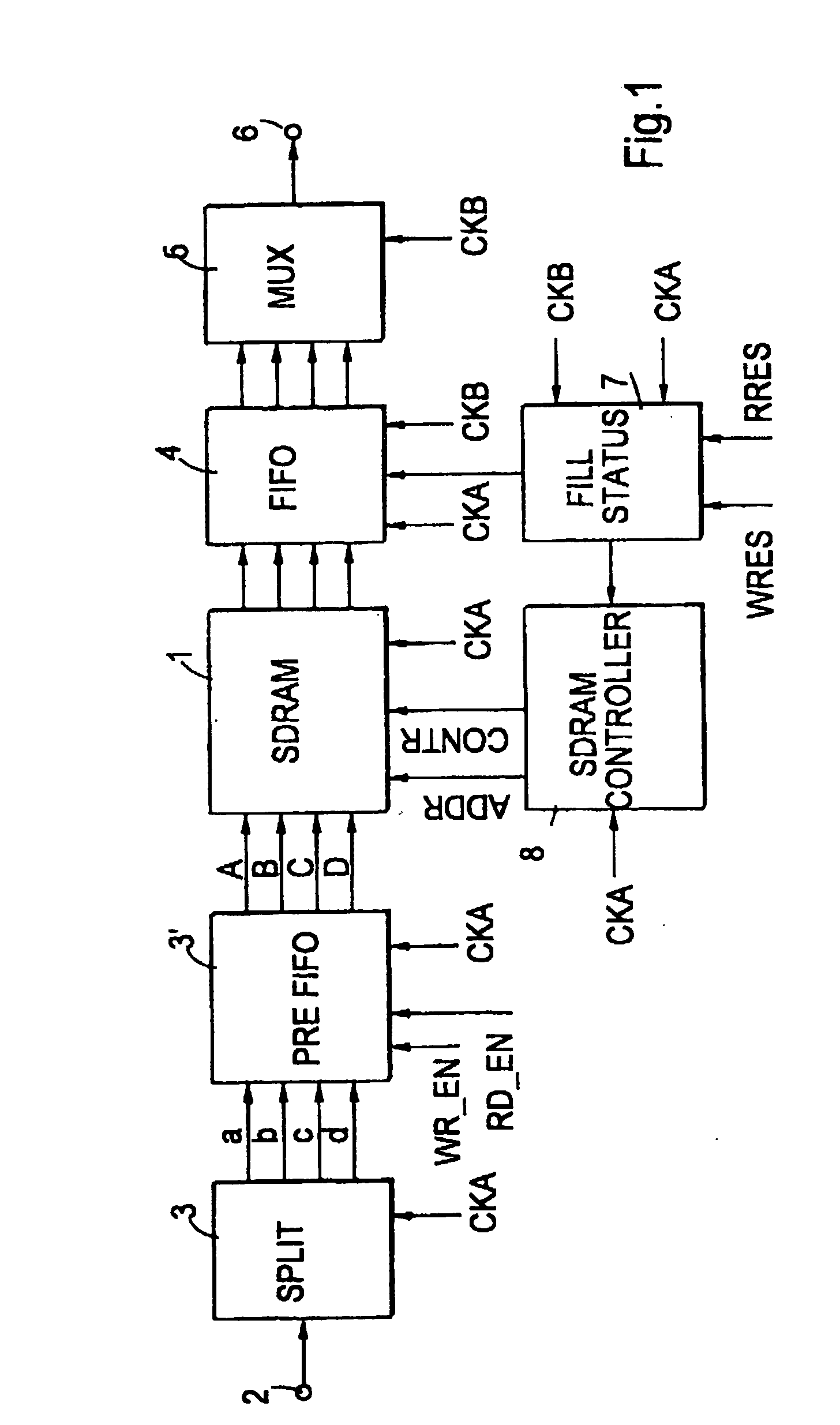
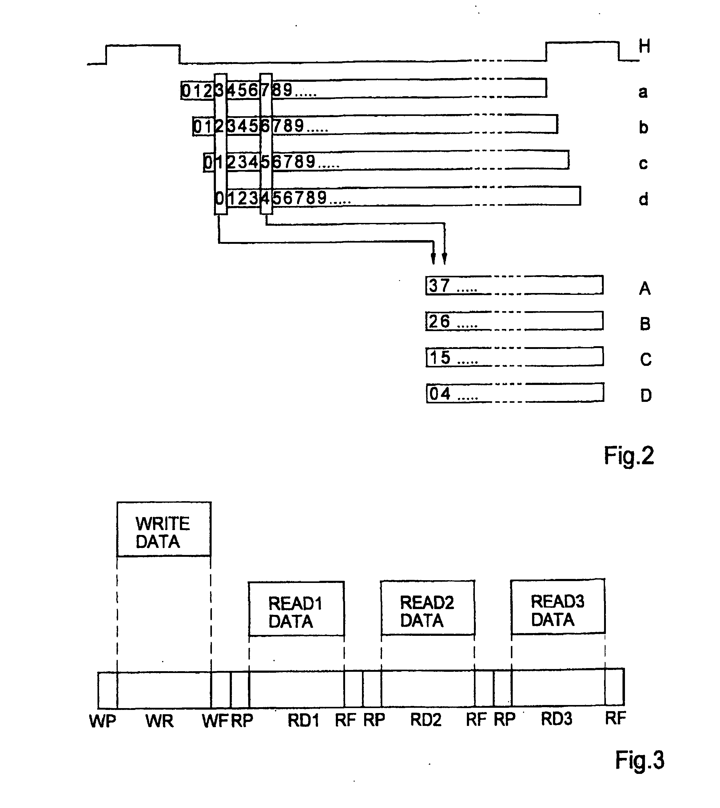
[0016] Digital video signals are fed to the arrangement according to FIG. 1 via an input 2, which signals are divided into four parallel data streams a, b, c, d in a circuit 3, which data streams are delayed relative to one another in each case by the duration of a pixel. In a buffer memory 3′—designated as PREFIFO in FIG. 1—every fourth pixel is taken from the data streams a, b, c, d, thereby producing compressed data streams A, B, C, D. To that end, the circuit 3 and the buffer memory 3′ are clocked with a clock CKA (also called Masterclock). The buffer memory 3′ receives suitable control signals WR_EN and RD_EN, which bring about the writing of every fourth pixel and the reading of each stored pixel.

[0017] This operation is illustrated diagrammatically in FIG. 2, the duration of a television line being indicated in line H using blanking pulses. Owing to the large ratio of the line period to the duration of a pixel, all of the signals and data streams are shown interrupted in FIG...


PUM


Abstract

The invention provides a method for storing video signals at a first rate and reading the stored video signals at a second rate. According to an embodiment of the method, the video signals to be stored are compressed. The compressed video signals are stored in a memory at a first rate. The compressed video signals a read from the memory into a buffer at the first rate. The video signals stored in the buffer are read from the buffer at a second rate such that the video signals are decompressed.

Description

TECHNICAL FIELD [0001] The invention relates to a method for storing video signals with the aid of a random access memory (SDRAM) that is operated synchronously during writing and reading, there being connected downstream of the random access memory a further memory (FIFO) with different frequencies for writing and reading. BACKGROUND OF THE INVENTION [0002] Television equipment and systems often require storage of video signals, and reading and writing are to be performed with different clocks. This is the case for example in film scanners and in synchronising devices. Memory modules in which reading can be effected with a different clock from writing are so-called FIFOs (First-In First-Out) for example. The latter have the disadvantage however, that they are available for the large capacity required for the abovementioned purposes only with a considerable outlay. Moreover, the maintenance of the temporal sequence of the signal, that is to say of the pixels, which is provided in th...

Claims


Application Information

Patent Timeline
Patent Type & Authority Applications(United States)
IPC IPC(8): G06F12/00G06F12/04H04N5/907H04N9/896
CPCH04N9/896
Inventor NOSKE, REINER
Owner MAGNOLIA LICENSING LLC
Why Eureka
Try Eureka