
Vibrating scoop basket

Inactive Publication Date: 2005-03-03
SHERIDAN CREEK ENTERPRISES
View PDF10 Cites 13 Cited by
  • Summary
  • Abstract
  • Description
  • Claims
  • Application Information

AI Technical Summary

Benefits of technology

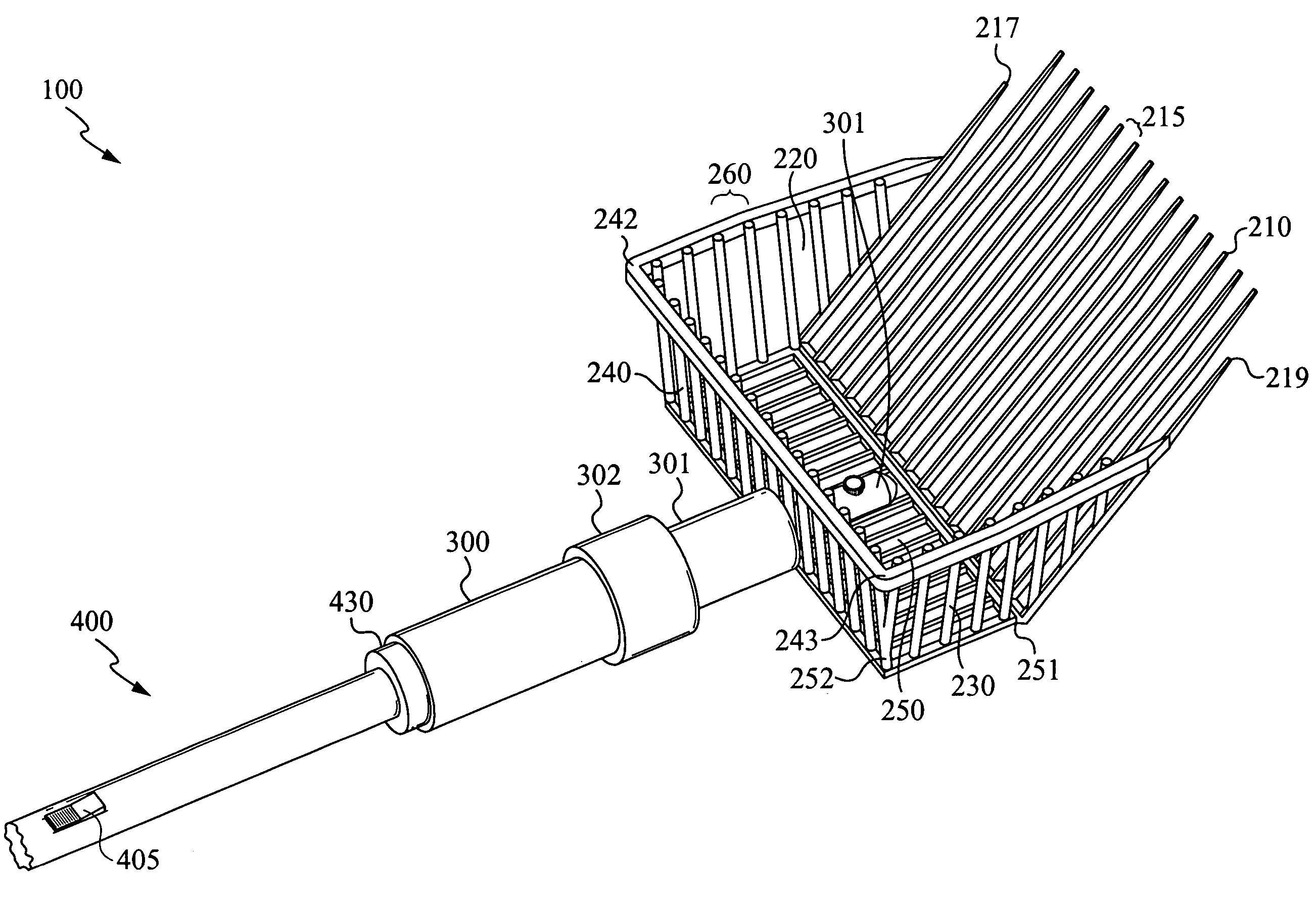
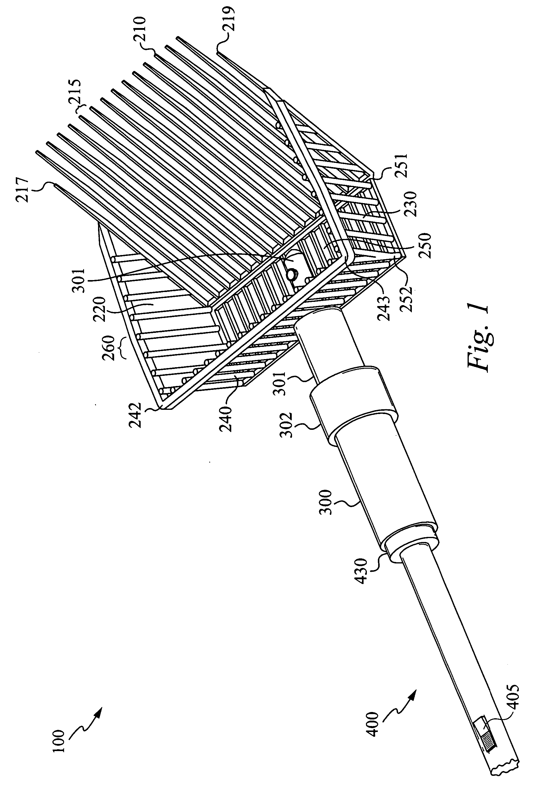
[0013] According to another aspect of the present invention, a method of making a device to extract manure from bedding material is disclosed. The method comprises the steps of providing a detachable scoop head having a plurality of apertures joined together to define a space. The apertures are sized to pass the bedding material there through but not the manure. The method further comprises the step of providing a detachable motor assembly coupled to the scoop head via a connector for vibrating the device

Problems solved by technology

This method was inefficient for many reasons.
The amount of wasted straw was high.
Further, the mixture of straw and manure was not very valuable as fertilizer since manure, not straw, is what makes the fertilizer potent.
The manual shaking of the rake-like device, however, is a strenuous process for the user as the load comprised of manure and bedding material can make the rake-like device difficult to scoop, raise and dump.
As mentioned before, the manual shaking of the device can be strenuous and can lead to short-term or long-term physical exhaustion, pain or disability.
Further, this method of removing the bedding material is inefficient, since shaking the device manually does not always maximize the removal of bedding material between the tines.
THE GREEN MACHINE TM teaches, however, that by using a large, expensive, and loud electrical vibrating machine, manure can be separated from bedding material.
Before using the sifter, the horses typically must be removed from the stable since the loud noise from the machine can excite or frighten the horses.
Although the machine can separate the manure from the bedding material, the drawbacks are apparent.
The machine is very expensive and heavy, and the tasks of removing the horses from the stalls and moving the heavy machine from stall to stall, before and after use of the machine, can be time-consuming and arduous.
Also, since the machine consumes much power, a battery pack is insufficient to power it.

Method used


Image

  • Vibrating scoop basket
  • Vibrating scoop basket
  • Vibrating scoop basket

Examples


Embodiment Construction

[0019] Reference will now be made in detail to the preferred and alternative embodiments of the invention, examples of which are illustrated in the accompanying drawings. While the invention will be described in conjunction with the preferred embodiments, it will be understood that they are not intended to limit the invention to these embodiments. On the contrary, the invention is intended to cover alternatives, modifications and equivalents, which may be included within the spirit and scope of the invention as defined by the appended claims. Furthermore, in the following detailed description of the present invention, numerous specific details are set forth in order to provide a thorough understanding of the present invention. However, it should be noted that the present invention may be practiced without these specific details. In other instances, well known methods, procedures and components have not been described in detail as not to unnecessarily obscure aspects of the present i...


PUM


Abstract

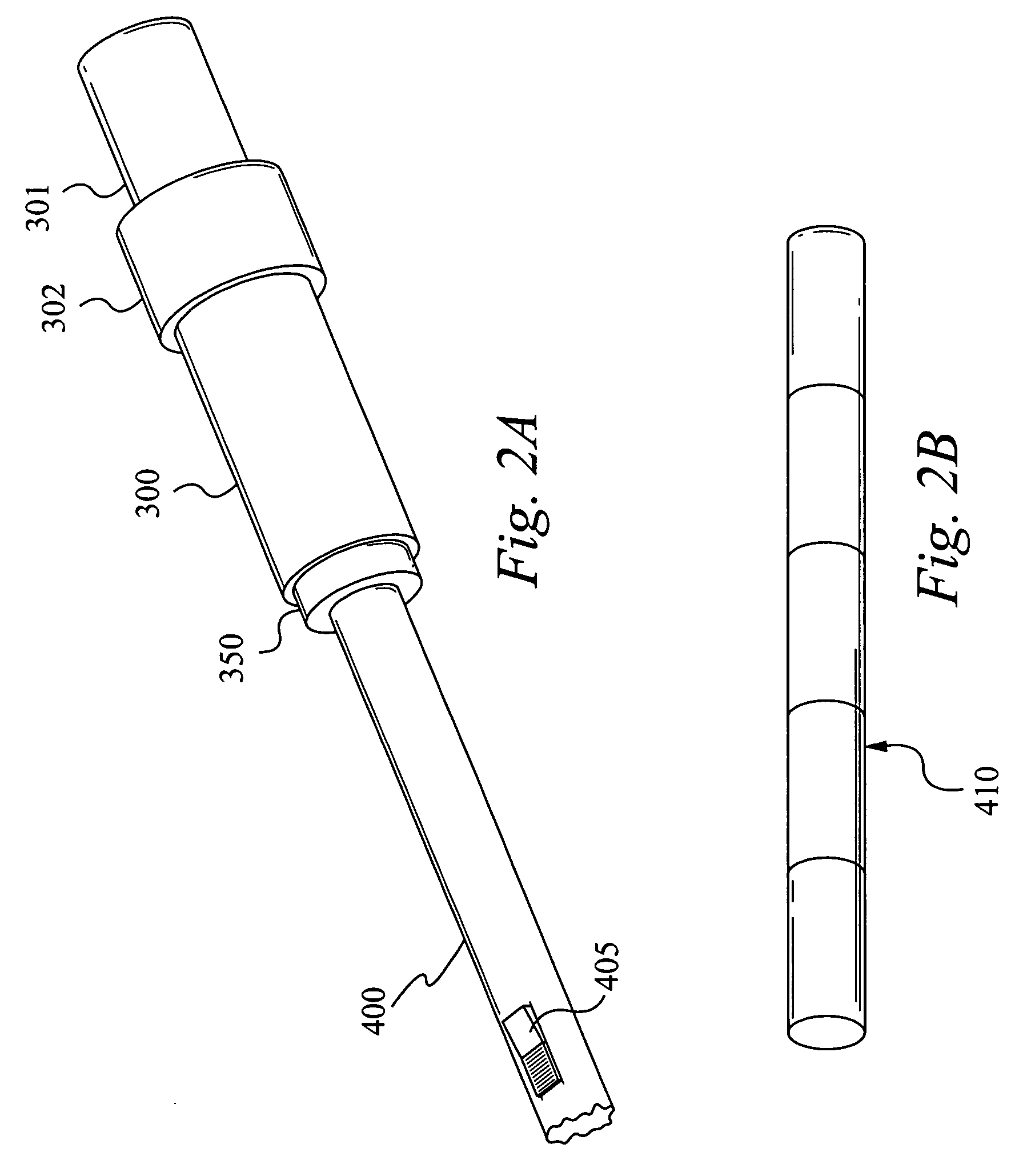
A device is used to extract manure from bedding material in a manner that maximizes the amount of manure extracted from the bedding material. The device includes a detachable scoop head having a plurality of apertures, a detachable motor assembly coupled to the scoop head for vibrating the device, and a detachable handle coupled to the motor assembly via a connector. The handle can include a power pack for supplying electrical power to the motor assembly. The apertures are preferably formed between elongated elements. The power pack, which can be housed within the handle, forms a counterweight to the scoop head when the device is lifted. The device can further include a stand having a release mechanism coupled to the device, wherein the release mechanism releases the stand in a fully deployed position to facilitate raising the scoop head.

Description

RELATED APPLICATION [0001] This patent application claims priority under 35 U.S.C. 119 (e) of the co-pending U.S. Provisional Patent Application Ser. No. 60 / 499,091 filed Aug. 28, 2003, and entitled “VIBRATING SCOOP BASKET”. The Provisional Patent Application, Ser. 60 / 499,091 filed Aug. 28, 2003, and entitled “VIBRATING SCOOP BASKET” is also hereby incorporated by reference.FIELD OF THE INVENTION [0002] The present invention relates to the field of excrement removal. More specifically, the present invention relates to the field of excrement removal utilizing a detachable hand-held device including a detachable motor assembly and detachable scoop head having a plurality of elongated elements. BACKGROUND OF THE INVENTION [0003] Typically horse stables utilize a bedding material such as saw chips, straw and other similar materials, to absorb the odor of manure and to make cleanup relatively simple. Originally, the process of removing the manure involved using a shovel-like device to sc...

Claims


Application Information

Patent Timeline
IPC IPC(8): A01B1/02A01K1/01
CPCA01K1/0114A01B1/02A01K1/01Y02A40/28
Inventor ROBERSON, GLENN A. JR.ROBERSON, GLENN A. IIIDOMATO, PAUL
Owner SHERIDAN CREEK ENTERPRISES
Learn More