Time switch

a time switch and time technology, applied in the field of time switches, can solve the problems of time-consuming operation and time-consuming to set the time, and achieve the effects of convenient time setting, preventing transmission, and easy discernibility

Inactive Publication Date: 2005-03-03
MATSUSHITA ELECTRIC WORKS LTD
View PDF9 Cites 4 Cited by
  • Summary
  • Abstract
  • Description
  • Claims
  • Application Information

AI Technical Summary

Benefits of technology

[0010] The present invention allows the time to be more conveniently set by manually turning the dial in either the motor-driven direction or the opposite direction thereto. This is made possible by the torque transmitted from the manually turned dial causing the ratchet mechanism to slip, thus preventing the transmission of torque from the dial to the motor. Moreover, the scheduling clips and contact points can be set to a mutually aligned condition by turning the contact points “on” or “off”, without turning the dial, by manually turning a control knob provided on the end of the cam shaft which projects outside of the case. Additionally, the present invention allows the condition of the contact points to be easily discerned from the radial position of the control knob.
[0011] Accordingly, the present invention provides improved operation of the time switch by allowing the time to be set by manually turning the dial in either the direction in which it is rotated by the motor, or the direction opposite thereto, at the time when the dial is being rotatably driven by the motor. This is made possible by the slippage of the ratchet mechanism preventing torque from the manually turned dial from being transferred to the motor. In addition, the contact points can be opened or closed, without turning the dial, by manually turning the cam shaft, through the manual turning of the control knob, to normally align the scheduling clip setting with the contact points.

Problems solved by technology

As a result, even though the sub-dial can be turned manually to set the time, it can only be turned in one direction, thereby making it time-consuming to set the time.
As a result, changing the time becomes a time-consuming operation.

Method used


Image

  • Time switch
  • Time switch
  • Time switch

Examples


Embodiment Construction

[0031] The particulars shown herein are by way of example and for purposes of illustrative discussion of the embodiments of the present invention only and are presented in the cause of providing what is believed to be the most useful and readily understood description of the principles and conceptual aspects of the present invention. In this regard, no attempt is made to show structural details of the present invention in more detail than is necessary for the fundamental understanding of the present invention, the description is taken with the drawings making apparent to those skilled in the art how the forms of the present invention may be embodied in practice.

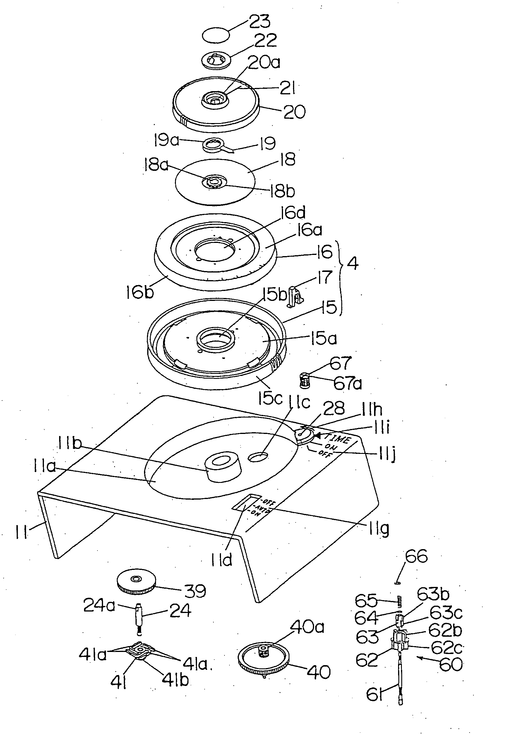
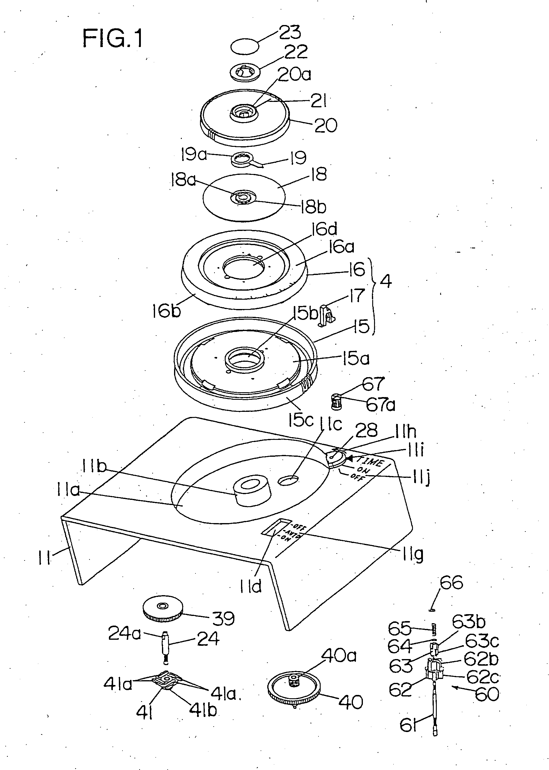
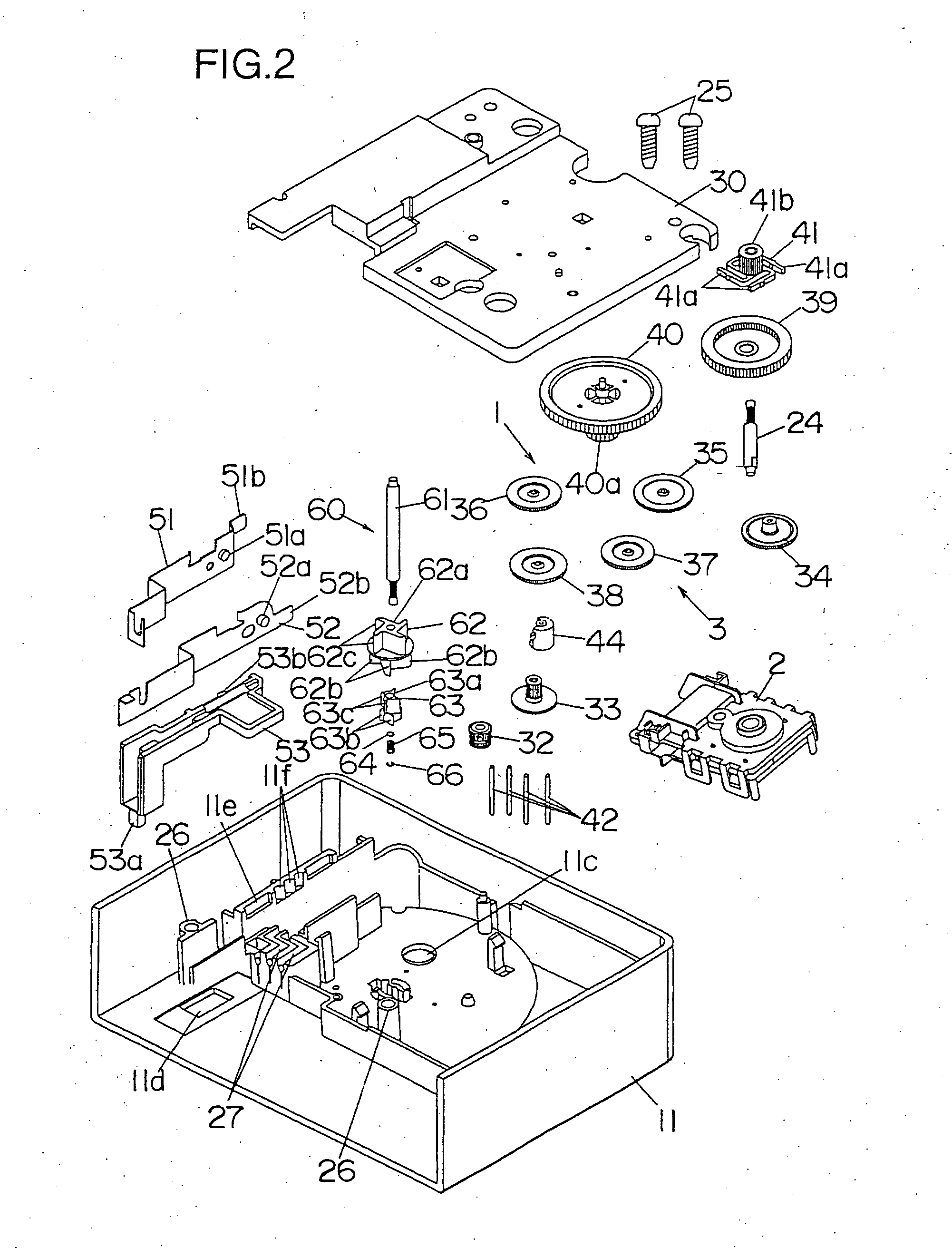
[0032] The following will describe embodiments of the invention with reference to the accompanying drawings. The first embodiment of the present invention will be described with reference to FIGS. 1 through 11 with positional references (top, bottom, right, left) being based on FIG. 3 unless otherwise specified.

[0033] As sh...


PUM


Abstract

A time switch that provides a convenient time setting method through a sub-dial that can be rotated clockwise or counter-clockwise. A ratchet device is constructed of multiple ratchet teeth formed at specific intervals on the rear surface of a drive gear, and pawls that extend from a pinion gear, the tip portions of the pawls engaging the multiple ratchet teeth. The ratchet device does not slip when the torque applied by the motor is sufficient to rotatably drive the dial, but slips when the torque applied to the ratchet device from the dial is greater than that applied by the motor. A control knob, which is attached to the tip of the cam shaft, may be turned to control the rotation of a switching cam which sets contact points to on or off positions.

Description

BACKGROUND OF THE INVENTION [0001] 1. Field of the Invention [0002] The present invention relates to a time switch whereby on and off conditions of internally installed contact points control the operation of an electrical load according to a desired time schedule. [0003] 2. Description of Background Information [0004] A conventional time switch, such as the type described in Japanese Kokai (laid open) Patent S63-29427, includes a modular structure assembled from a motor that rotates at a uniform speed, a ratchet gear driven by a gearwheel transmission powered by the motor, and a first gear that meshes with the ratchet gear. The time switch also includes a sub-dial that rotates clockwise at a rate of one revolution per hour relative to the rotation of the ratchet gear, a gear that meshes with a second gear attached to the rotating shaft of the sub-dial, a dial that rotates clockwise once during a twenty four hour period relative to the rotation of the sub-dial, a scheduling clip wit...

Claims


Application Information

Patent Timeline
Patent Type & Authority Applications(United States)
IPC IPC(8): H01H43/10G04C23/02G04C23/08H01H43/00H04M1/24
CPCG04C23/08G04C23/02
Inventor MUROI, HIROAKITODOKORO, TAKAYUKI
Owner MATSUSHITA ELECTRIC WORKS LTD
Why Eureka
Try Eureka