
Intermediate bulk container

a technology of intermediate bulk containers and bulk containers, which is applied in the direction of containers, pliable tubular containers, tray containers, etc., can solve the problems of high cost, inability to support the stack structure, and the materials from which the container components are made are expensively over-designed compared to what would be required, so as to inhibit the skewing of the poles and increase the length of the sockets

Inactive Publication Date: 2005-03-03
ALMAR PACKAGING INT
View PDF8 Cites 26 Cited by
  • Summary
  • Abstract
  • Description
  • Claims
  • Application Information

AI Technical Summary

Benefits of technology

[0012] The pole engaging formations on the pallet base and the pole location member are preferably sockets in which the end portions of the poles are frictionally engaged, in use, to inhibit skewing of the poles relatively to the components with which they are engaged. Conveniently, the pole location member includes outwardly projecting formations which face the pallet base and through which the pole sockets pass into the member to increase the length of the sockets in which the upper end portions of the posts are frictionally engaged, in use. A portion of the lengths of the pole sockets in the pallet base, from their mouths in the upper surface of the pallet base, may be dimensioned and shaped to receive the pole location member projecting formations when the pole location member is placed on the pallet base.

Problems solved by technology

Problems associated with all known containers of the above types, other than perhaps those of the rigid box type, are that: (a) the containers are difficult to stack and when stacked result in an unstable stack structure.
This is principally due to the flexibility of the container bags and the fluid nature of their contents which they generally contain, (b) a further difficulty with the stacking of these containers, particularly when they are filled with a high density material such as granular fertilizer, liquids and so on, is, if they are at all stackable, that the vertical load of the upper containers in the stack is transferred directly through the material in the container bags to the lower containers in the stack.
This vertical load transmission could in many cases exceed the hoop strength of the reinforcing side beams and the flexible bag material between them to destroy the lower containers in the stack unless the materials from which the container components are made are expensively over-designed compared to what would be required in a single free standing container.
This becomes a highly expensive problem when the containers contain processed fresh produce which is stored and frozen in suitably insulated and refrigerated storage facilities.
Additionally, it would certainly be unwise to attempt to convey, by means of a forklift or the like, even two of the containers which are stacked one on the other without the provision of at least some form of side support for the containers on the forklift tines, and (c) the containers for various products are generally designed by variation of their bag material and the circumferential spacing between and the nature of the side beams, to be specific to a designated load material having a specific density.
This problem makes it necessary for the organisation which fills the container bags with various materials to expensively keep in stock container types suited to the transportation and storage of the various materials.

Method used


Image

  • Intermediate bulk container
  • Intermediate bulk container
  • Intermediate bulk container

Examples


Embodiment Construction

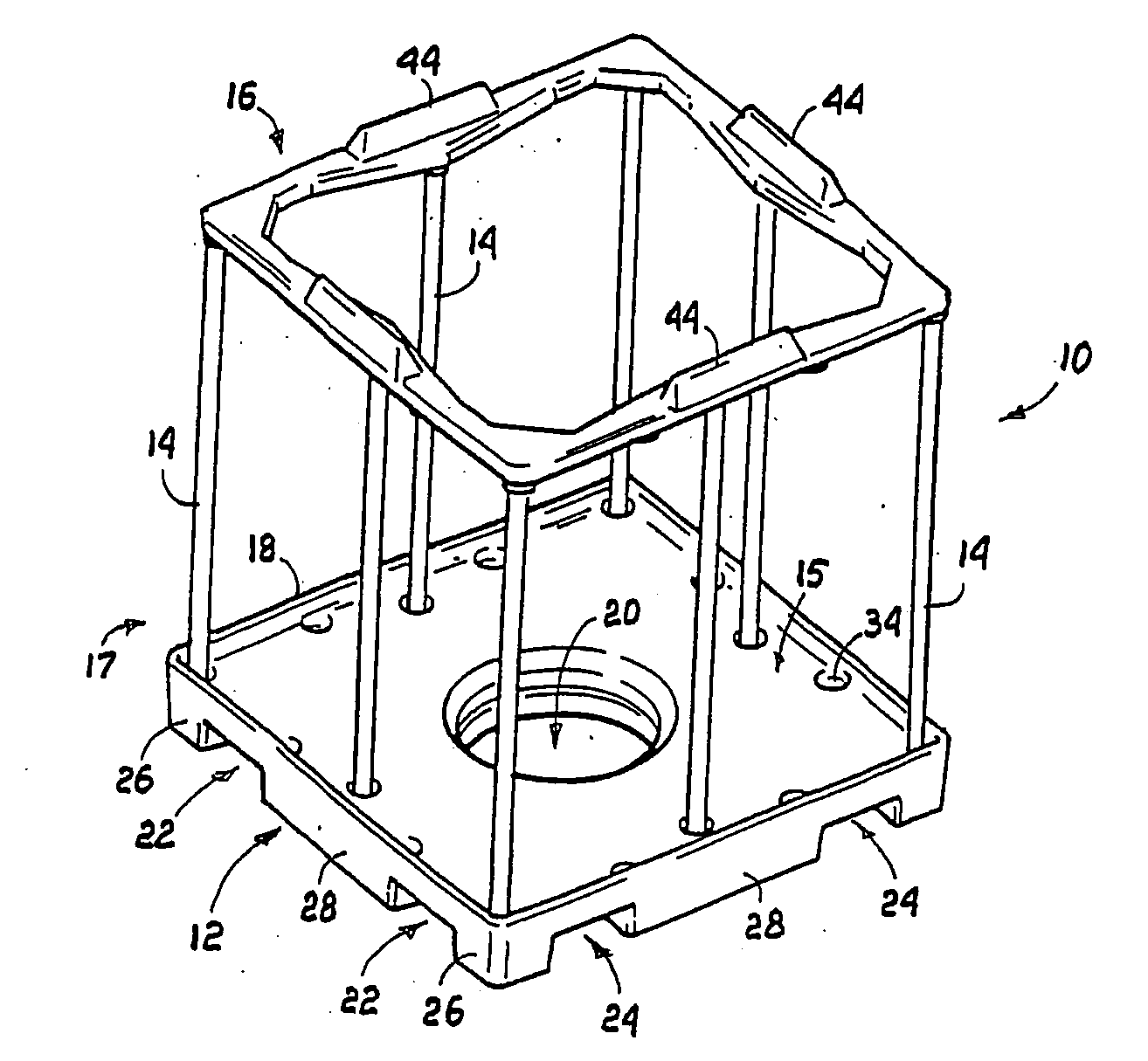
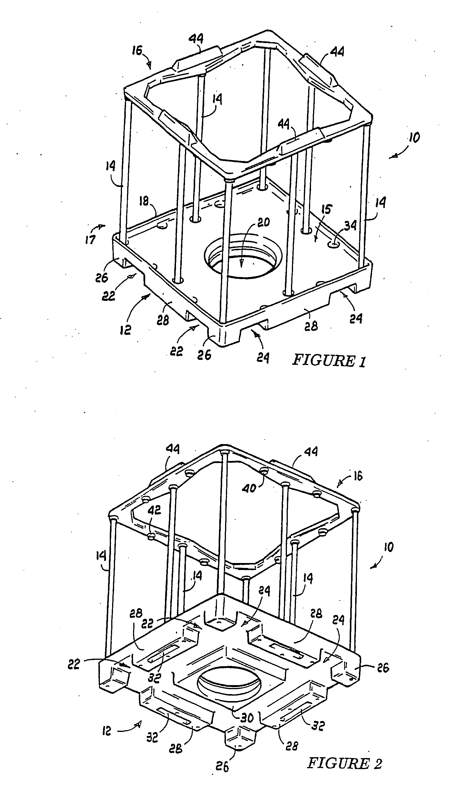
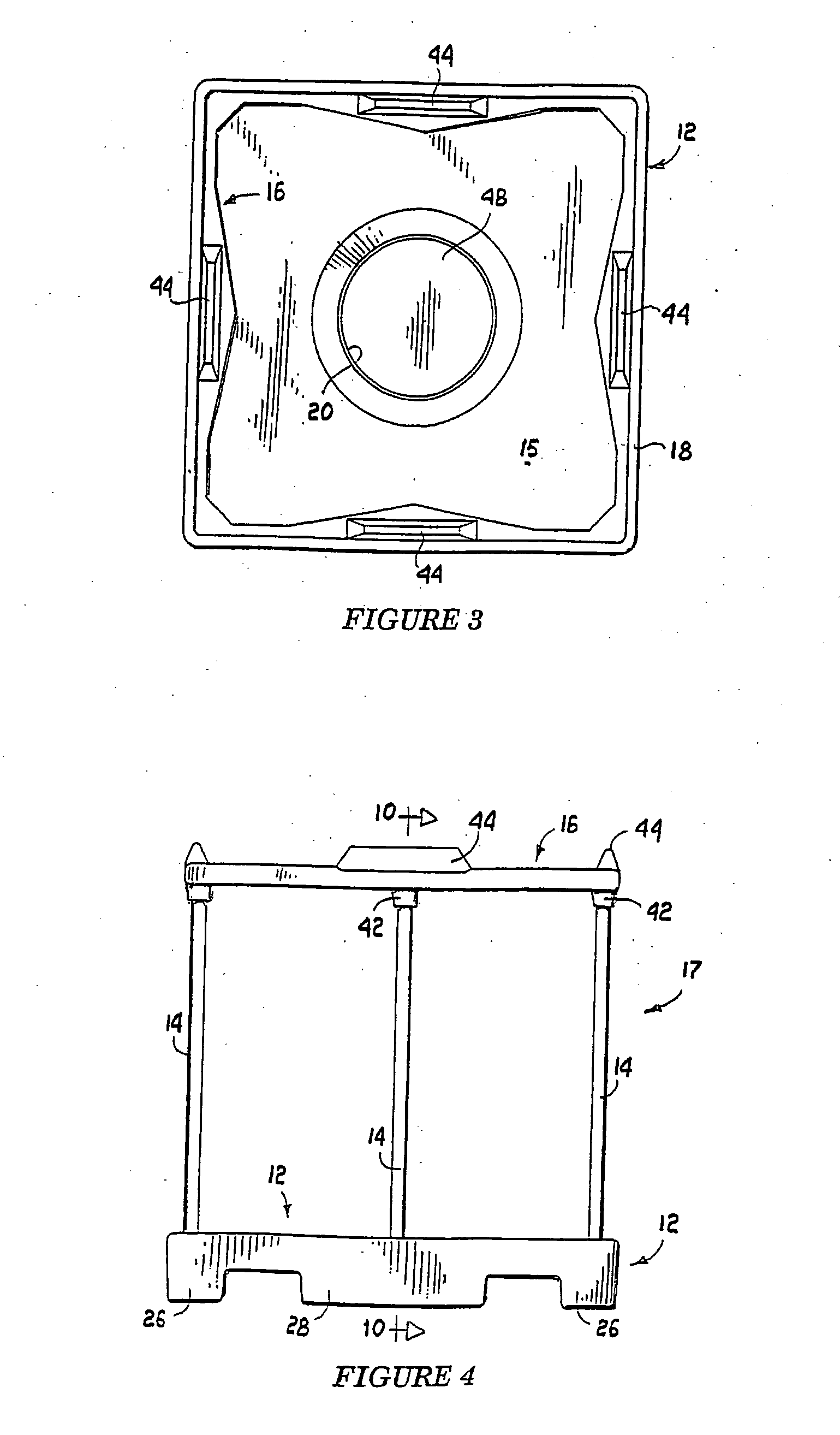
[0043] The intermediate bulk container 10 of the invention is shown in the drawings to include a forklift pallet base 12, restraining poles 14 and a pole locating member or ring beam 16 which together provide a support cage 17 for a storage container.

[0044] The pallet base 12 is hollow rotor moulded from a suitable plastics material such as linear low density polyethylene and is most clearly shown in FIGS. 1, 2, 7 and 8 to include a flat upper surface 15, an upstanding peripheral rim 18 and a centrally located circular discharge aperture 20.

[0045] The underside of the pallet base, as is most clearly seen in FIGS. 2 and 8, includes two pairs of parallel sided recesses 22 and 24 with each pair of recesses being dimensioned and spaced to provide forklift tine recesses which are accessible from any one of the four sides of the pallet base. The pairs of recesses 22 and 24 define between them four substantially square corner support plinths 26, elongated support plinths 28 between the c...


PUM


Abstract

An intermediate bulk container (10) comprising a storage container (50) which is made from a suitable flexible material, a forklift pallet base (12) including pole engaging formations (34) on its upper surface (15) which are arranged about its periphery (18), a plurality of poles (14) the lower ends of which are releasably engageable with formations (34) on the pallet base (12) to provide a support cage for the storage container (50), a holed pole location member (16) including pole engaging formations (40) with which the upper ends of the poles (14) are engageable to lock the poles (14) together to inhibit transverse outward bulging of the storage container (50) from between the poles (14) and to preserve the container support cage (17) against a load in the storage container (50) with the underside of the pallet base (12) and the upper surface of the pole locating member (16) including formations (32, 44) which are releasably engageable with compatible formations on containers below and above it in a stack.

Description

FIELD OF THE INVENTION [0001] This invention relates to a knock-down intermediate bulk container of the type which comprises a bulk storage bag which is made from a flexible material for containing particulate material, discreet objects or liquid and a support structure in which the bag is located to inhibit lateral bulging of the loaded bag in use. BACKGROUND TO THE INVENTION [0002] The bag support structure of most known containers of the above type consist of peripherally spaced side beams which extend between top and bottom panels of the container for the purpose of minimising transverse bulging of the container bag wall in use. [0003] The top and bottom panels of the various containers are made from a flexible material which could be that from which the container bag is made, a corrugated cardboard, timber, plastic or metal. [0004] The container side beams are made from corrugated cardboard which is formed into side wall support panels or elongated posts, timber panels, plastic...

Claims


Application Information

Patent Timeline
Patent Type & Authority Applications(United States)
IPC IPC(8): B65D19/38B65D30/04B65D30/10B65D77/06B65D88/22B65D90/12B65D90/20
CPCB65D77/061B65D19/385B65D77/06B65D19/38
Inventor THORPE, JOHN RICHARD
Owner ALMAR PACKAGING INT
Learn More