

Electric parking brake system and method for controlling the same
a technology of parking brakes and brakes, which is applied in the direction of braking systems, braking components, transportation and packaging, etc., can solve the problems of increasing costs, complicated structure and procedures, and the inability of motors to generate stable braking force, and achieves simple structure and stable braking force
- Summary
- Abstract
- Description
- Claims
- Application Information
AI Technical Summary
Benefits of technology
Problems solved by technology
Method used
Image

Examples
Embodiment Construction
[0014] A preferred embodiment of the present invention will now be described with reference to FIGS. 1 to 3.
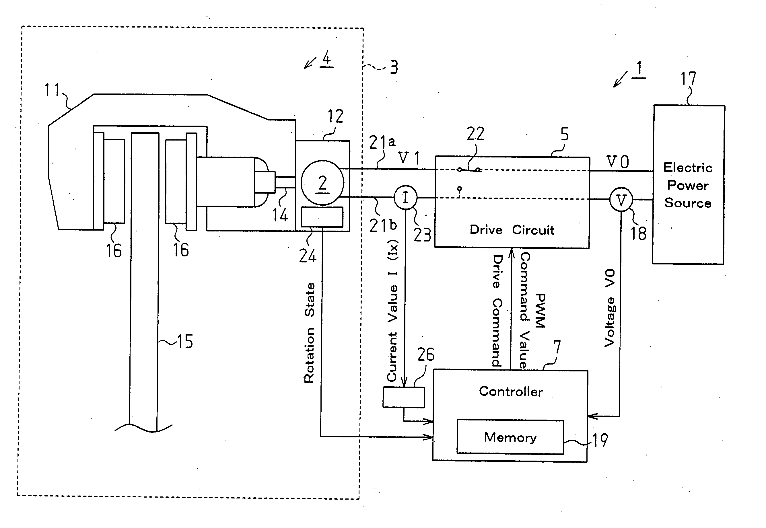
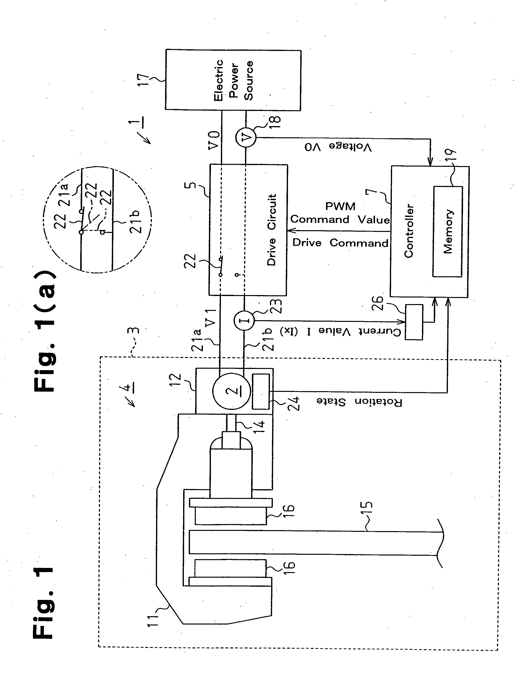
[0015]FIG. 1 shows an electric parking brake system 1 mounted to a vehicle having wheels 3 (only one is shown). The electric parking brake system 1 includes electric parking brakes 4 (only one is shown), a drive circuit 5, and a controller 7 that controls the drive circuit 5. Each electric parking brake 4 is mounted to one of at least two of the wheels 3. Each electric parking brake 4 has a power source, which is an electric motor 2. Using the motor 2, each electric parking brake 4 applies braking force to the corresponding wheel 3. The drive circuit 5 supplies drive electricity to the motors 2.
[0016] Each electric parking brake 4 includes a braking portion 11 for applying braking force to the corresponding wheel 3, and an actuator 12 that actuates the braking portion 11. The actuator 12 converts forward and reverse rotations of the motor 2 into reciprocation of an output sh...
PUM
 Abstract
Description
Claims
Application Information