
Flexible synthesizer for multiplying a clock by a rational number

a flexible and rational technology, applied in the field of frequency synthesizers, can solve the problems of large filter components, affecting the performance of the synthesizer, and the inability to adapt to the application of conventional plls,

Active Publication Date: 2005-03-03
MEDIATEK INC
View PDF3 Cites 16 Cited by
  • Summary
  • Abstract
  • Description
  • Claims
  • Application Information

AI Technical Summary

Benefits of technology

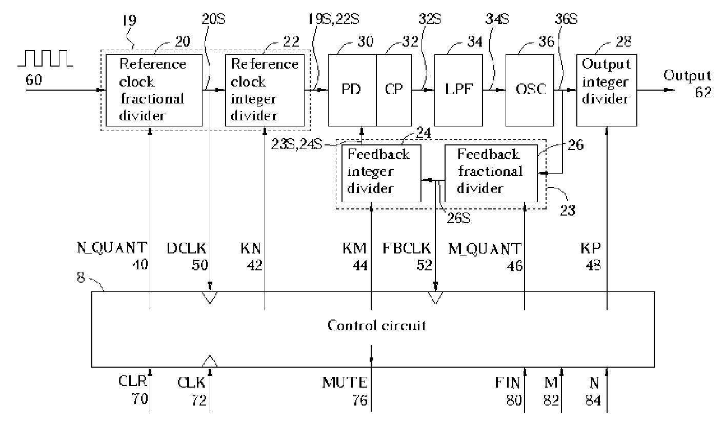
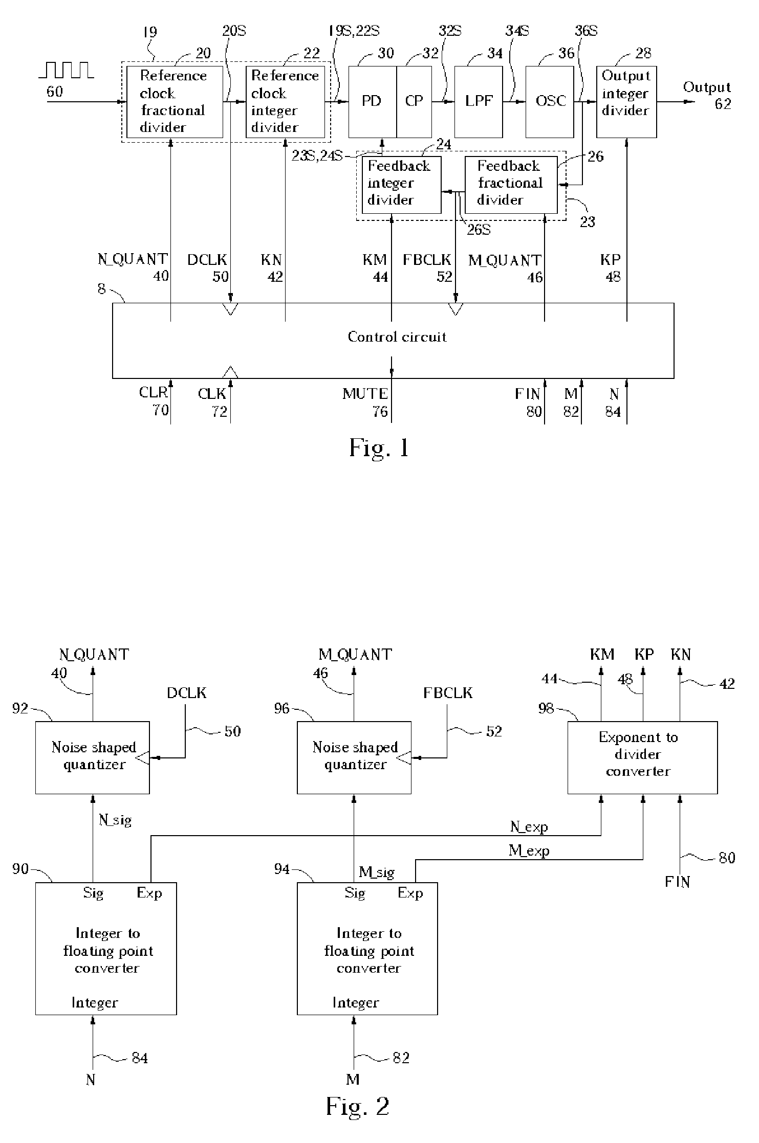
The present invention provides a frequency synthesizer that can output a precise frequency even when the input or feedback dividers are large numbers. It also features low output clock jitter and maximizes the output frequency range while minimizing the range of the variable-frequency oscillator in the PLL. The frequency synthesizer includes a phase detector, an oscillator, a first divider module, and a second divider module. The first divider module generates the feedback input by dividing the variable frequency signal by a first time-varying value, while the second divider module generates the reference input by dividing the reference signal by a first time-varying value.

Problems solved by technology

However, the switching speed and resolution of synthesizers are becoming critically important, and conventional PLLs are ill-suited to these applications because they suffer an inability to simultaneously provide fast frequency switching and high resolution without substantial design complexity.
This classic design has several limitations when the input and feedback divisors are large values.
Second, as a consequence of this, the filter components must be large, possibly requiring the use of external components.
Third, the low bandwidth makes the PLL susceptible to noise, notably for example the standard 60 Hz power line noise.
Fourth, the variable-frequency oscillator frequency limits the possible input and output frequencies of the circuit when the range of possible divisor values is large.
Fifth, such a circuit may have high power consumption.
Sixth, the use of external components drives up the cost of production and increases hardware space requirements.

Method used


Image

  • Flexible synthesizer for multiplying a clock by a rational number
  • Flexible synthesizer for multiplying a clock by a rational number
  • Flexible synthesizer for multiplying a clock by a rational number

Examples


Embodiment Construction

[0023] In the following detailed description of the preferred embodiments, reference is made to the accompanying drawings that form a part hereof, and in which is shown by way of illustration specific preferred embodiments in which the invention may be practiced. The preferred embodiments are described in sufficient detail to enable those skilled in the art to practice the invention, and it is to be understood that other embodiments may be utilized and that logical changes may be made without departing from the spirit and scope of the present invention. The following detailed description is, therefore, not to be taken in a limiting sense, and the scope of the present invention is defined only by the appended claims.

[0024] Refer to FIG. 1, which illustrates a frequency synthesizer in accordance with one preferred embodiment of the present invention. The frequency synthesizer comprises a first divider module 23, a second divider module 19, a phase detector 30, a charge pump 32, a loo...


PUM


Abstract

A frequency synthesizer that includes two fractional dividers, two noise-shaped quantizers, three integer dividers, a PLL, an algorithm embodied in control logic, and an adjustment means. The noise-shaped quantizers are used to quantize two fractional (fixed-point) values, derived from the divider control words, into time-varying values. The dividers and PLL are used to generate an output signal by means of multiplying a reference signal by the quotient of the divider control word values. Accordingly, the frequency synthesizer of the present invention can provide a very precise output clock, with the average output frequency being the input frequency multiplied by the quotient of the two divider control words, and with high jitter stability.

Description

CROSS REFERENCE TO RELATED APPLICATIONS [0001] The application claims the benefit of U.S. Provisional Application No. 60 / 498,697, filed Aug. 29, 2003, and included herein by reference.BACKGROUND OF INVENTION [0002] 1. Field of the Invention [0003] The present invention generally relates to a frequency synthesizer. More specifically, the present invention relates to a frequency synthesizer featuring high precision, wide bandwidth, low jitter, a broad frequency output range, and an integrated PLL with a limited oscillator frequency range. [0004] 2. Description of the Prior Art [0005] Modern multimedia entertainment systems are placing ever increasing demands on the resolution, bandwidth, and switching speed of frequency synthesizers. In the past, these requirements have been satisfied by the conventional phase-locked loop (PLL) synthesizer. The fundamental advantage of PLLs has been their ability to synthesize an output clock signal of high spectral purity that may be tuned over a wid...

Claims


Application Information

Patent Timeline
Patent Type & Authority Applications(United States)
IPC IPC(8): H03L7/08H03L7/16H03L7/18H03L7/197
CPCH03L7/1976
Inventor SMITH, STERLING
Owner MEDIATEK INC
Learn More