Robust predictive deconvolution system and method

Inactive Publication Date: 2005-03-03
THE UNITED STATES OF AMERICA AS REPRESENTED BY THE SECRETARY OF THE NAVY
View PDF1 Cites 17 Cited by
  • Summary
  • Abstract
  • Description
  • Claims
  • Application Information

AI Technical Summary

Benefits of technology

The Reiterative Minimum Mean-Square Error (RMMSE) predictive deconvolution system and method of the invention provide high-fidelity impulse response estimation compared to other systems such as matched filtering and LS. In one embodiment, the RMMSE estimator reiteratively estimates the MMSE filter for each spe

Problems solved by technology

Predictive deconvolution provides a means to obtain the high spatial resolution of a short, high bandwidth pulse without the need for very high peak transmit power, which may not be feasible.
However, upon further inspection one finds that the LS received signal model does not completely characterize the received return sign

Method used


Image

  • Robust predictive deconvolution system and method
  • Robust predictive deconvolution system and method
  • Robust predictive deconvolution system and method

Examples


Embodiment Construction

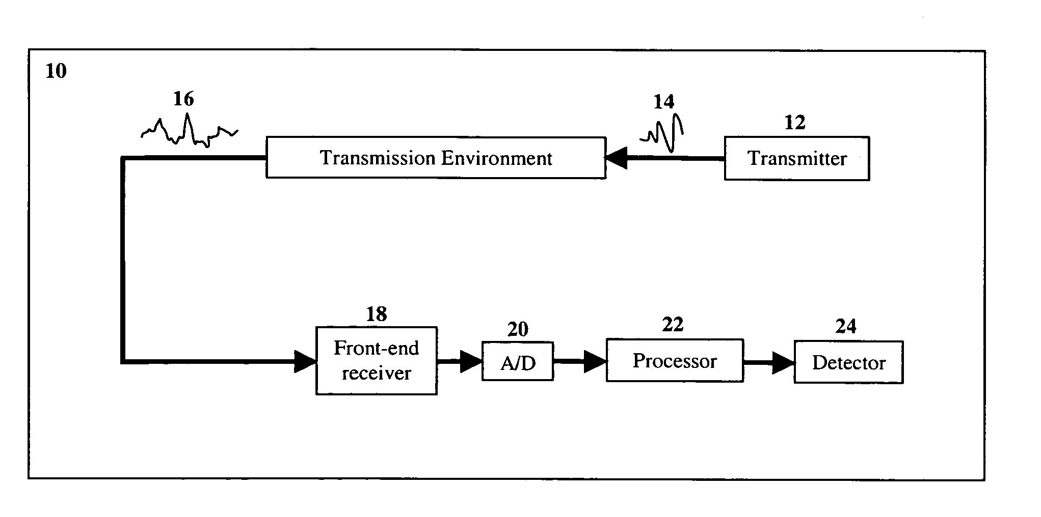
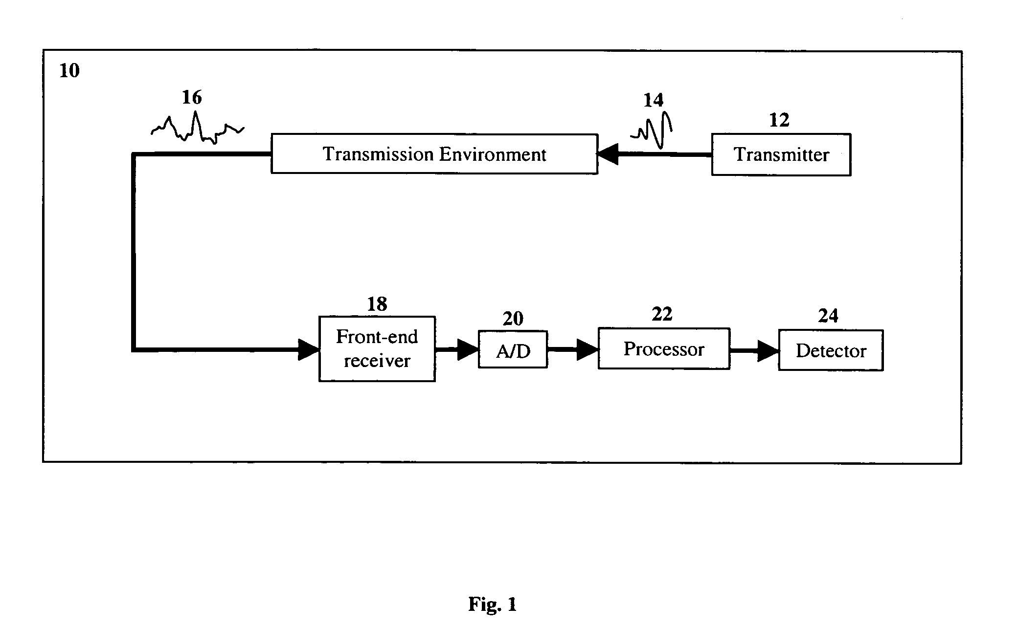
Definitions: The term “convolution” means the process that yields the output response of an input to a linear time-invariant system, such as is described and defined in J. G. Proakis and D. G. Manolakis, Digital Signal Processing:Principles, Algorithms, and Applications, 3rd Ed., pp. 75-82, Prentice Hall: Upper Saddle River, N.J. (1996), incorporated herein by reference. The term “deconvolution” as used herein means the process that given the output of a system determines an unknown input signal to the system. See Id. at p. 355, incorporated herein by reference. The term “scatterer” means something in the path of a transmitted waveform that causes a significant reflection (relative to the noise) back to the receiver of the sensor.

Referring now to FIG. 1, a predictive deconvolution system 10 includes a transmitter 12 for transmitting a phase or frequency modulated pulse (or waveform) 14 that, upon interacting with its transmission environment's unknown impulse response 16 (to be e...


PUM


Abstract

A method for processing a received, modulated pulse (i.e. waveform) that requires predictive deconvolution to resolve a scatterer from noise and other scatterers includes receiving a return signal; obtaining L+(2M−1)(N−1) samples y of the return signal, where y(l)={tilde over (x)}T(l)s+ν(l); applying RMMSE estimation to each successive N samples to obtain initial impulse response estimates [{circumflex over (x)}1{−(M−1)(N−1)}, . . . ,{circumflex over (x)}1{−1},{circumflex over (x)}1{0}, . . . ,{circumflex over (x)}1{L−1},{circumflex over (x)}1{L}, . . . ,{circumflex over (x)}1{L−1+(M−1)(N−1)}]; computing power estimates {circumflex over (ρ)}1(l)=|{circumflex over (x)}1(l)|2 for l=−(M−1)(N−1), . . . ,L−1+(M−1)(N−1); computing MMSE filters according to w(l)=ρ(l)(C(l)+R)−1s, where ρ(l)=|x(l)|2 is the power of x(l), and R=E[v(l)vH(l)] is the noise covariance matrix; applying the MMSE filters to y to obtain [{circumflex over (x)}2{−(M−2)(N−1)}, . . . ,{circumflex over (x)}2{−1},{circumflex over (x)}2{0}, . . . ,{circumflex over (x)}2{L−1},{circumflex over (x)}2{L}, . . . ,{circumflex over (x)}2{L−1+(M−2)(N−1)}]; and repeating (d)-(f) for subsequent reiterative stages until a desired length-L range window is reached, thereby resolving the scatterer from noise and other scatterers. The RMMSE predictive deconvolution approach provides high-fidelity impulse response estimation. The RMMSE estimator can reiteratively estimate the MMSE filter for each specific impulse response coefficient by mitigating the interference from neighboring coefficients that is a result of the temporal (i.e. spatial) extent of the transmitted waveform. The result is a robust estimator that adaptively eliminates the spatial ambiguities that occur when a fixed receiver filter is used.

Description

TECHNICAL FIELD This invention relates to a method and system for predictive deconvolution, which is otherwise known as pulse compression in radar applications. More particularly, the invention relates to robust predictive deconvolution using minimum mean-square error reiteration. BACKGROUND ART In many sensing applications, such as radar pulse compression, sonar, ultrasonic non-destructive evaluation for structural integrity, biomedical imaging, and seismic estimation, it is desirable to estimate the impulse response of an unknown system by driving the system with a known signal having a finite temporal extent. The process of separating the known signal from the received output of the system in order to estimate the unknown impulse response is known as predictive deconvolution. Predictive deconvolution provides a means to obtain the high spatial resolution of a short, high bandwidth pulse without the need for very high peak transmit power, which may not be feasible. This is acco...

Claims


Application Information

Patent Timeline
IPC IPC(8): G01S7/292G01S13/28
CPCG01S13/284G01S7/2921
Inventor BLUNT, SHANNON D.GERLACH, KARL R.
Owner THE UNITED STATES OF AMERICA AS REPRESENTED BY THE SECRETARY OF THE NAVY
Why Eureka
Try Eureka