Polarized material inspection apparatus and system

Inactive Publication Date: 2005-03-03
KARP JOHN +1
View PDF13 Cites 11 Cited by
  • Summary
  • Abstract
  • Description
  • Claims
  • Application Information

AI Technical Summary

Benefits of technology

[0028] It is another aspect of the invention to provide a device and system for irradiating a surface that eliminates the

Problems solved by technology

However, none of the prior art devices or methods provide a means or method of illuminating a surface and then view either surface or subsurface reflectance at the discretion of the user.
The prior art also requires elaborate and often fixed setups to perform any type of surface analysis.
There is little teaching of portable units that would enable the imaging to be done in remote locations or manipulate the illuminator source with respect to the object being viewed.
Finally, most prior art systems are costly and, therefore, are not practical for those with limited resources.
The biased magnetic field induces a rotation of the plane of polarization of the incident projected light such that viewing the reflection through a linear polarizer will render flaws visible.
This apparatus, although providing distinct advantages over prior art systems, has certain attributes that have been seen as drawbacks in some circumstances.
First, the use of a head-mounted apparatus, often connected by wires to a power supply, has been found to restrict the movement of physicians utilizing the apparatus.
Second, the mounting of a hot

Method used


Image

  • Polarized material inspection apparatus and system
  • Polarized material inspection apparatus and system
  • Polarized material inspection apparatus and system

Examples


Embodiment Construction

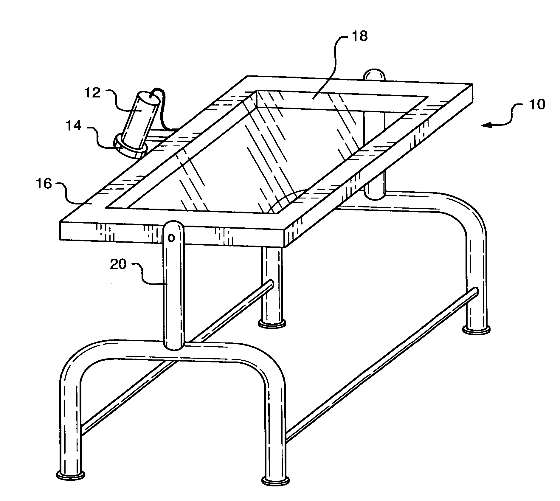
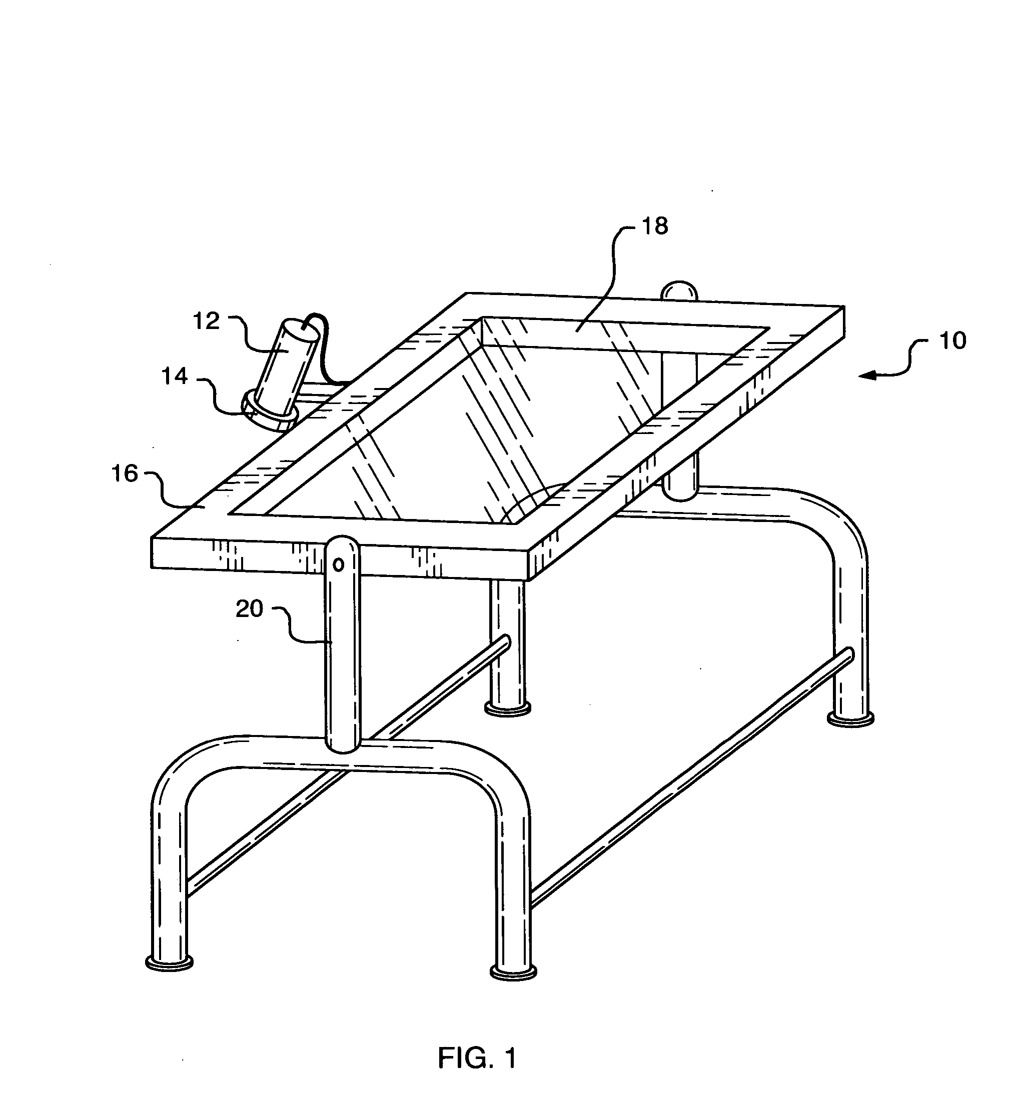
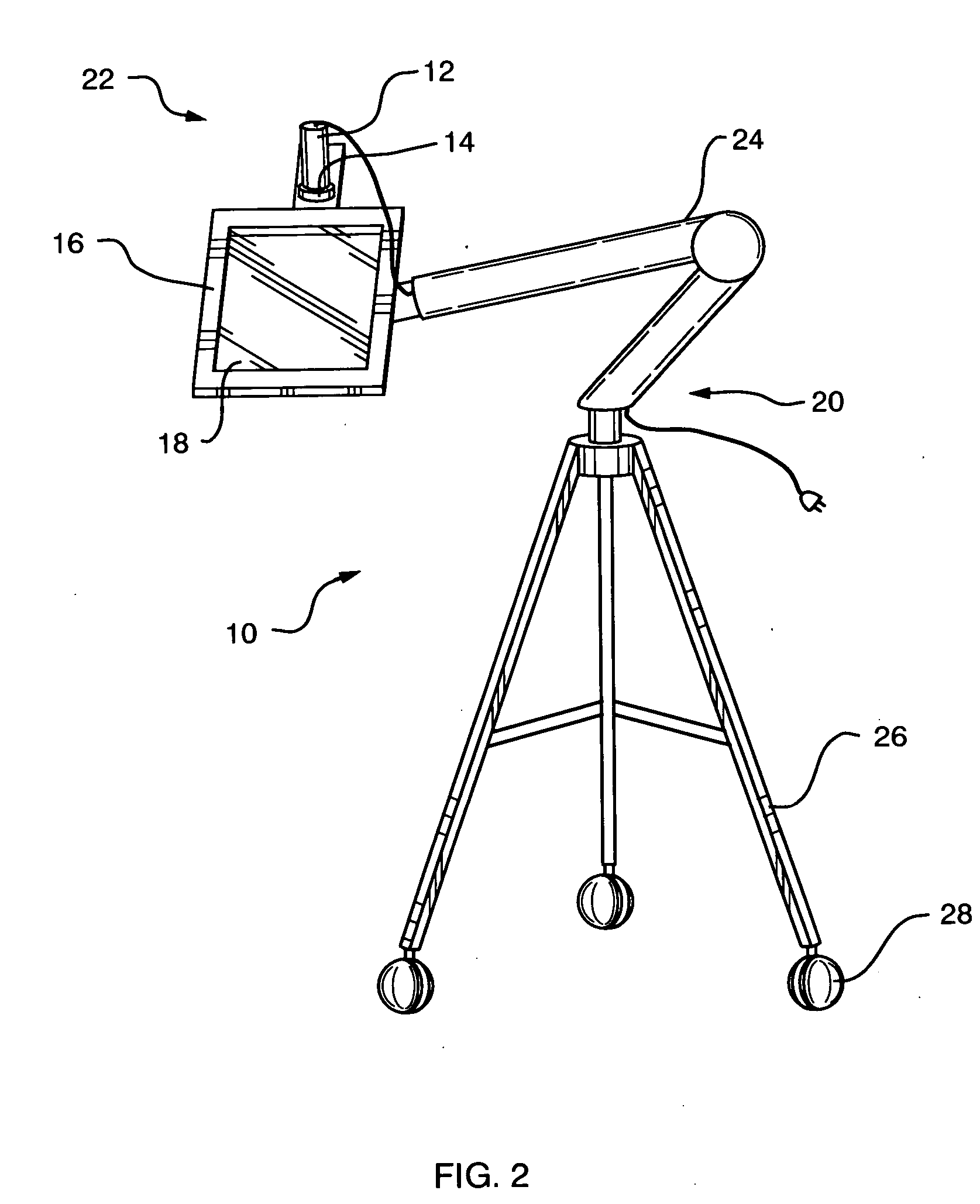
[0042] Referring first to FIG. 1, an isometric view of the basic embodiment of the device 10 is shown. The basic embodiment includes a light source 12, a first polarizing filter 14 disposed within the optical path of the light source, a frame 16 into which a second polarizing filter 18 is disposed, and a support 20 for positioning the frame 16 such that an object (not shown) may be viewed through the second polarizing filter 18. The first polarizing filter 14 and second polarizing filter 14 each have a plane of polarization, and the first polarizing filter 14 and / or the second polarizing filter 18 are rotatable through a ninety degree arc such that the planes of polarization may be adjusted to be parallel or orthogonal to one another.

[0043] As shown in FIG. 1, it is preferred that the light source 12 be attached to the frame 16 and positioned such that the light from the light source 12 is reflected back through the second polarizing filter 18. In this embodiment, the first polariz...


PUM


Abstract

A polarized material inspection device that includes a light source, a first polarizing filter disposed within the optical path of the light source, a frame into which a second polarizing filter is disposed, and a support for positioning the frame such that an object may be viewed through the second polarizing filter. In the preferred embodiment, the first polarizing filter is rotatable through a ninety degree arc such that planes of polarization may be adjusted to be parallel or orthogonal to one another. The preferred embodiment also includes a light illumination assembly having a rotatably mounted linear polarizer at the polarizing output end. This light assembly is attached to a portion of the frame and may be adjusted such that the beam of light is directed to the desired portion of the surface. Within the frame is mounted a fixed linear polarizing filter of sufficient size to allow the entire illuminated surface to be viewed. The frame is mounted to an adjustable support arm that is attached to a tripod or other support to allow the apparatus to be fixed during a given procedure.

Description

[0001] This application is a Continuation-in-Part of co-pending U.S. patent application Ser. No. 09 / 543,650, filed Apr. 5, 2000, which claims the benefit of U.S. Provisional Patent Application Ser. No. 60 / 129,645, filed Apr. 16, 1999.FIELD OF THE INVENTION [0002] The present invention relates to an apparatus and system for evaluating the surface and sub-surface properties of a surface and, in particular, to an apparatus and system for irradiating the surface with adjustable polarized light and viewing the optical reflectance through a polarizing viewer. BACKGROUND OF THE INVENTION [0003] Light reflected from skin has two components: regular reflectance, or “glare” arising from the surface, and light backscattered from within the tissue. The regular reflectance contains the visual cues related to surface texture, whereas the backscattered component contains the cues related to pigmentation, erythema, infiltrates, vessels and other intracutaneous structures. Unlike the backscattered c...

Claims


Application Information

Patent Timeline
IPC IPC(8): G01N21/21
CPCG01N21/21
Inventor KARP, JOHNPELLETIER, DOMINIC
Owner KARP JOHN
Why Eureka
Try Eureka