Method and apparatus for providing polarization insensitive signal processing for interferometric sensors

a technology of interferometer and signal processing, applied in the field of interferometer, can solve the problems of fiber inducing phase noise, imbalance equal to time-delay experience, and unbalanced interferometer

Active Publication Date: 2005-03-03
OPTOPLAN
View PDF5 Cites 39 Cited by
  • Summary
  • Abstract
  • Description
  • Claims
  • Application Information

AI Technical Summary

Benefits of technology

In a first embodiment of the invention, a pulsed source for the interferometric sensor array is used. The SOP of the interrogation pulses is controlled individually so that two interfering pulses may originate from interrogation pulses that have different SOP such that at least four components of the detected signal can be separated and processed to extract a phase measurement from the response Jones matrix without error caused by polarization induced fading or noise caused by birefringence fluctuations in the lead fibers.

Problems solved by technology

If the nominal path lengths are different, the interferometer is said to be unbalanced, and the imbalance is equal to the difference in time-delay experienced by the light propagating in the two paths.
Thus, if the sensor is birefringent, fluctuations in the SOP of the lead fiber will induce phase noise.
The noise performance of such sensor arrays may be limited by the polarization fluctuations in the lead fiber induced by environmental effects.
The polarization-induced phase noise can be eliminated using depolarized light; however this method does not solve the fading problem.
Furthermore, the Faraday rotating mirrors may be expensive, space consuming, and sensitive to extreme thermal, electromagnetic and other environmental conditions.
When several sensors are multiplexed, this method requires input-polarization control of each multiplexed sensor, which makes it impractical for remote and inaccessible sensor arrays.
These techniques require relatively complex systems to provide feedback signals to the polarization controller.
Thus, the minimum detection bandwidth required for this method is much larger than necessary for CW interrogation of interferometric sensors.
This high detection bandwidth makes this method impractical for TDM two-pulse interrogation.

Method used


Image

  • Method and apparatus for providing polarization insensitive signal processing for interferometric sensors
  • Method and apparatus for providing polarization insensitive signal processing for interferometric sensors
  • Method and apparatus for providing polarization insensitive signal processing for interferometric sensors

Examples


second embodiment

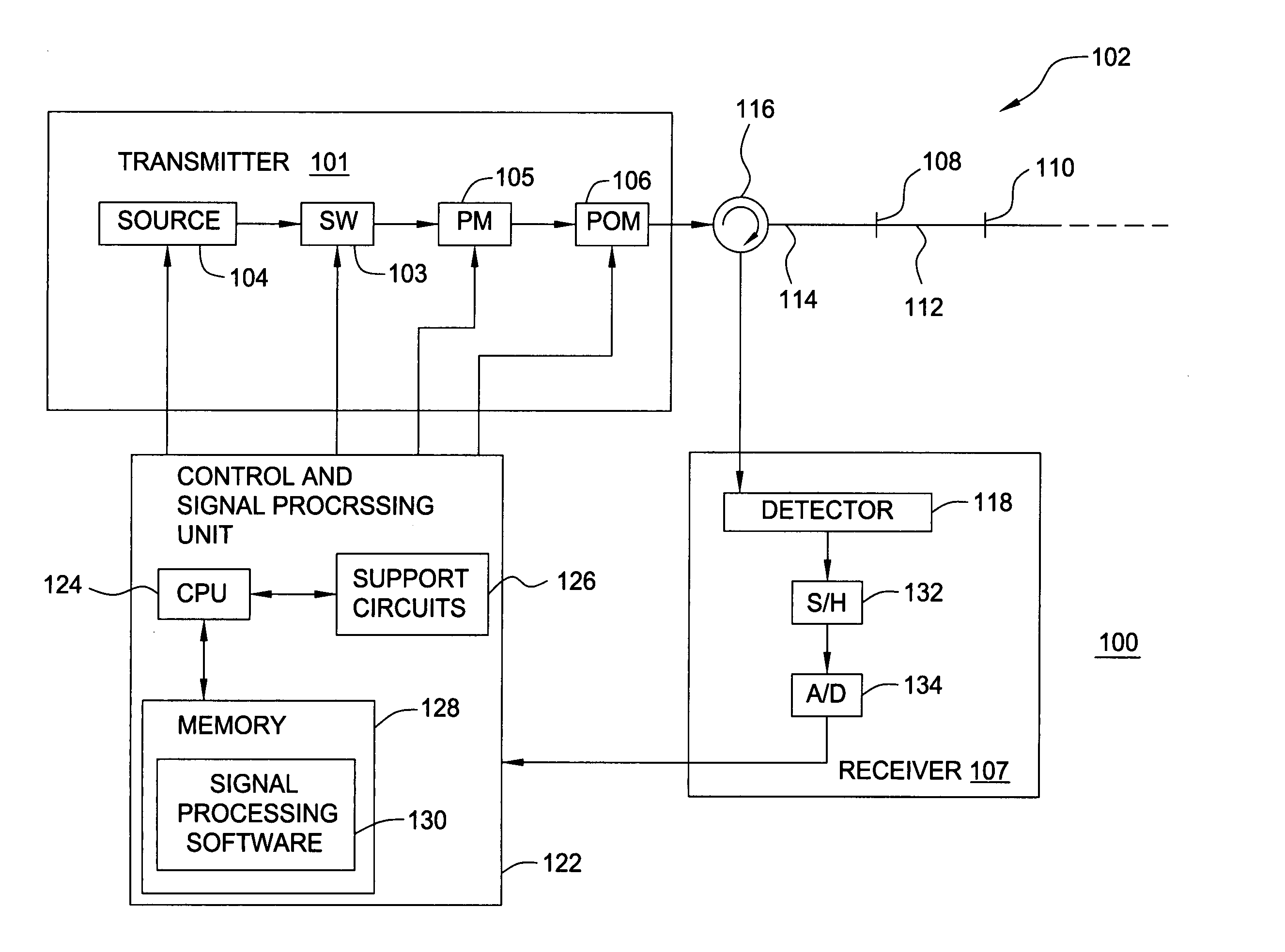
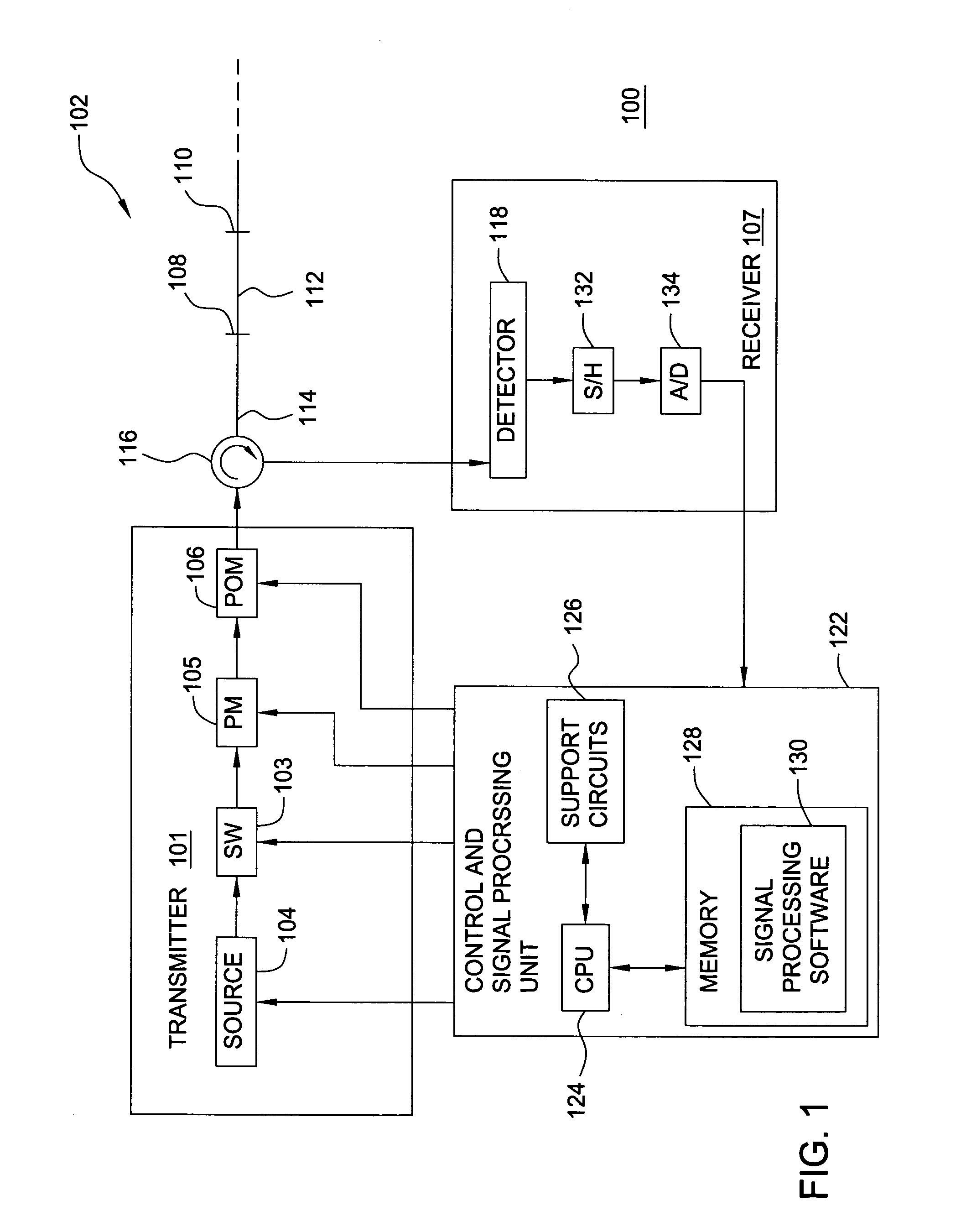
The first embodiment described above is based on having the SOPs of the interrogation pulses controlled individually so that two interfering pulses may originate from interrogation pulses that have different SOP. This embodiment only works for pulsed interrogation systems. FIG. 3 depicts a block diagram of the present invention. In this embodiment, the two interfering beams may originate from the same transmitter output SOP, and the modulation of the transmitter output SOP can be made independent of the sensor imbalance. This allows for this method to be used in combination with both pulsed TDM and other multiplexing techniques that employs a CW (continuous wave) source such as frequency division multiplexing (FDM) and wavelength division multiplexing (WDM). In FDM, the laser frequency is swept over a range larger than the free spectral range of the interferometers, and different electrical signal frequencies are generated at the detector corresponding to different delay difference ...

fifth embodiment

In a fifth embodiment, the response matrix R can be found if the transmitter output SOP is modulated through a set of states that can be represented by at least two independent Stokes vectors and set of eigenpolarizations of the polarization diversity receiver that can be represented by at least three independent Stokes vectors. This is the reciprocal version of the forth embodiment, and this embodiment will give the same set of measured signal components as the forth embodiment if the up-lead fiber replaces the down-lead fiber and visa versa.

In FDM systems, the laser can be swept over a range much larger than the free spectral range of the sensor, which gives a fringe signal with an electrical frequency at the detector that is proportional to the delay of the sensor. The phase of the fringe signal relative to the source frequency is a measure for the sensor phase. The frequency of the fringe signal provides a measurement of the delay of the sensor. See X. Wan et. al “Fiber-Bragg-G...


PUM


Abstract

A method and apparatus that uses specific source modulation and detectors to detect a response that carries information about a system response matrix associated with each sensor in a interferometric sensor array and extracting a sensor response in a manner that eliminates polarization-induced signal fading and that is insensitive to lead fiber birefringence fluctuations.

Description

BACKGROUND OF THE INVENTION 1. Field of the Invention The present invention relates to interferometric sensors and, more particularly, the present invention relates to a method and apparatus for providing polarization-induced phase noise insensitive signal processing for interferometric sensors. 2. Description of the Related Art When using interferometric sensors, the input light to the sensor is split into two paths (i.e., a reference path and a sensor path) and recombined. The reference path is a path from the transmitter to the receiver via a first path of the sensor, while the sensor path is the path from the transmitter to the receiver via a second path of the sensor. The path that experiences a length change due to a disturbance within the sensor, usually the longest path, forms the sensor path and the other path forms the reference path. The portions of fiber that are common to both the sensor path and the reference path define the lead fibers. The light beams that travel...

Claims


Application Information

Patent Timeline
Patent Type & Authority Applications(United States)
IPC IPC(8): G01D5/34G01D5/353
CPCG01D5/345G01D5/35383G01D5/35303
Inventor WAAGAARD, OLE HENRIKRONNEKLEIV, ERLEND
Owner OPTOPLAN
Why Eureka
Try Eureka