Compact linear air pump and valve package

a linear, air pump technology, applied in the field of pumps, can solve the problems of motor wear and noise, increase the footprint as well as the cost of components and assembly, and reduce the reliability of the pump, reduce the interconnection, and reduce the effect of sealing or eliminating certain components

Inactive Publication Date: 2005-03-03
THOMAS IND INC
View PDF11 Cites 36 Cited by
  • Summary
  • Abstract
  • Description
  • Claims
  • Application Information

AI Technical Summary

Benefits of technology

[0016] Thus, the present invention provides a compact pump unit in which a single housing contains both the pump and valve components. The entire interior of the housing becomes pressurized during operation of the pump such that no tubes or other conduit are necessary to transfer the pressurized air exhausted from the valve heads to the valve assembly. This compact package affords a number of benefits, particularly in eas

Problems solved by technology

While both of these units are designed to be relatively compact and quiet as well as produce sufficient air flow volume and pressure for use in an air bed, they each have attributes that make them somewhat disadvantageous.
The '756 device has a relatively complicated drive arran

Method used


Image

  • Compact linear air pump and valve package
  • Compact linear air pump and valve package
  • Compact linear air pump and valve package

Examples


Embodiment Construction

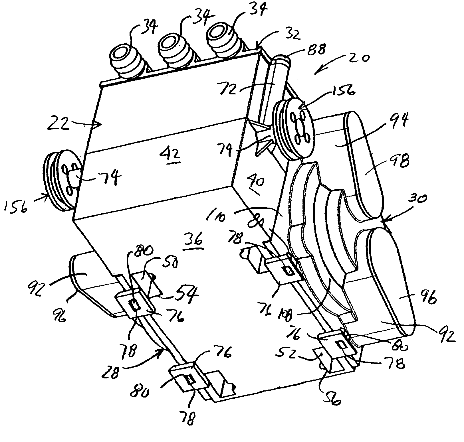
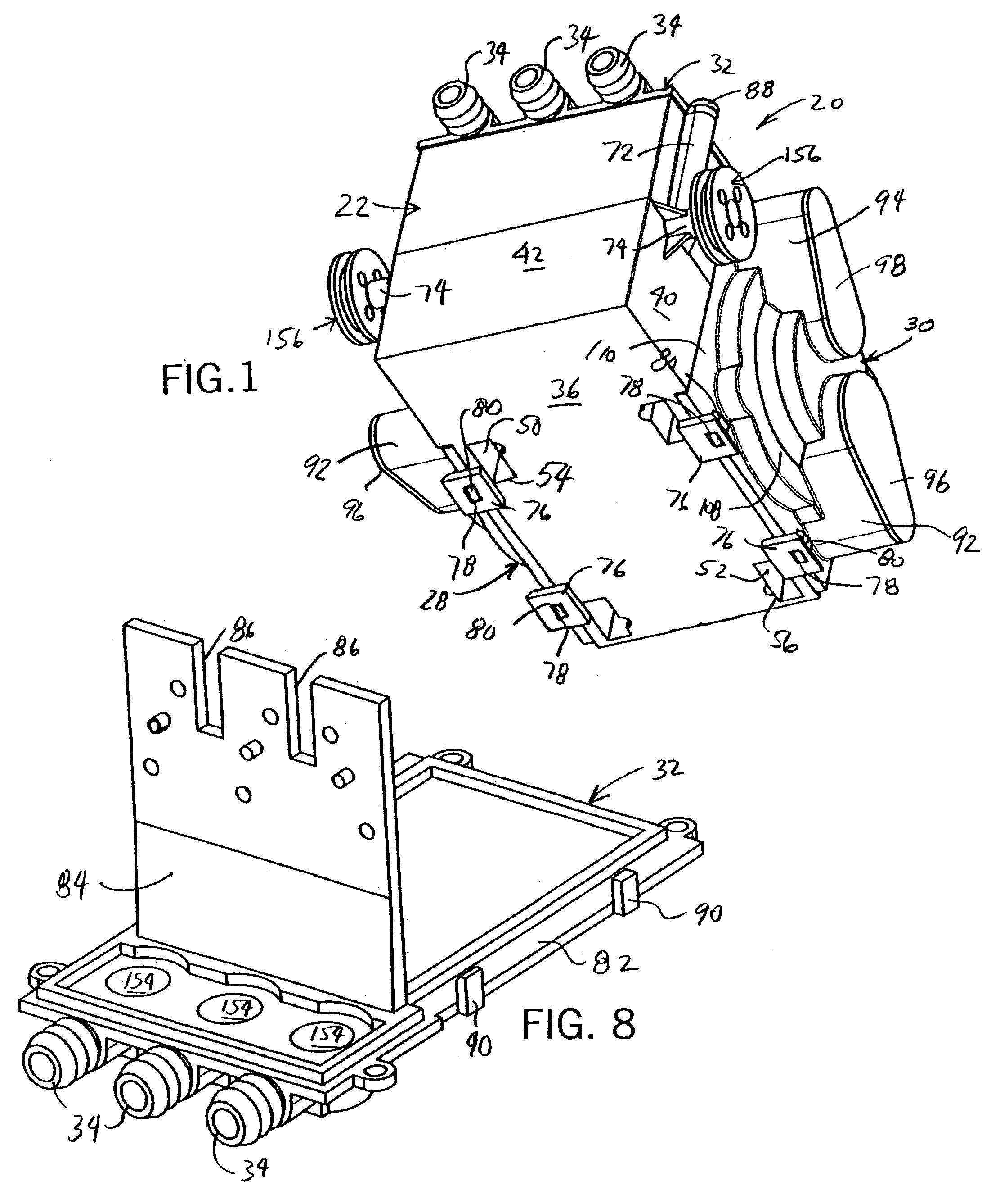
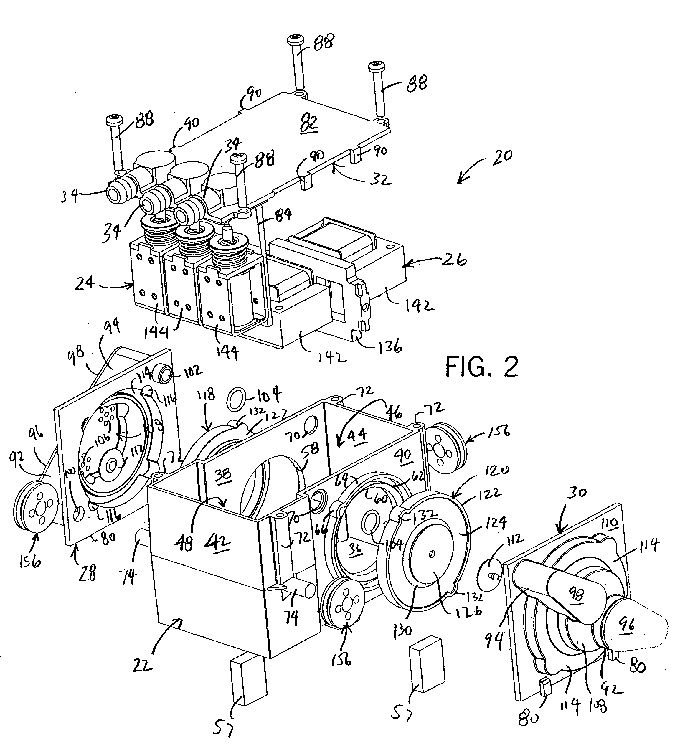
[0034] A preferred version of the pump of the present invention will now be described in detail. Referring to FIGS. 1-8, a pump unit 20 generally includes a pressure housing 22 containing a solenoid valve assembly 24 and a linear pump assembly 26. Air flow to and from the pump assembly 26 pass through two valve heads 28 and 30 mounted to the pressure housing 22. The pressure housing 22 also includes a separate cover 32 having three hose barb type fittings 34 for connecting three air lines to the interior of the pressure housing 22 when opened by the solenoid valve assembly 24.

[0035] Referring to FIGS. 1 and 6, the pressure housing 22 is a box-like, preferably plastic, structure with a bottom wall 36, two upright side walls 38 and 40 and two upright ends walls 42 and 44. The upright walls define an open top side that is enclosed by the cover 32. The pressure housing 22 and its cover 32 create an enclosed interior having a piston chamber 46 and a valve chamber 48. The interior is des...


PUM


Abstract

A compact air pump and valve package includes pump and valve assemblies integral with a pressure housing defining inlet ports and a plurality of fittings for connecting air lines to an interior of the pressure housing. The linear diaphragm pump assembly has a permanent magnetic shuttle mounting two diaphragms reciprocated by an electromagnet. The valve assembly has a plurality of solenoid valves disposed within the pressure housing, each solenoid valve being operable to control flow into or out of the pressure housing through an associated one of the plurality of fittings. Thus, no tubes or hoses are required to transfer air from the pump assembly to the valves. The housing has special mounts to isolate vibration arising from movement of the shuttle.

Description

CROSS-REFERENCE TO RELATED APPLICATIONS [0001] Not applicable. STATEMENT OF FEDERALLY SPONSORED RESEARCH OR DEVELOPMENT [0002] Not applicable. BACKGROUND OF THE INVENTION [0003] 1. Technical Field [0004] The present invention relates to pumps and in particular to linear diaphragm air pumps. [0005] 2. Description of the Related Art [0006] Air compressors and pumps are well known. Some are large reciprocating piston and cylinder pumps for high flow volume commercial or industrial applications and others are compact units for lesser flow home applications. One example of the latter is inflating a bladder membrane, such as an air mattress for an air bed. Pumps for inflating and deflating air mattresses need to provide rapid pressurization while being both compact and quiet. [0007] U.S. Pat. No. 5,606,756 discloses an example of a pump for an air mattress application. This pump has a motor rotated shaft mounting two canted flanges at opposite ends with push and pull sets of diaphragm pis...

Claims


Application Information

Patent Timeline
IPC IPC(8): A47C27/10F04B35/04F04B45/047
CPCA47C27/082F04B45/047F04B35/045A47C27/10
Inventor LI, WENJUNHEIDENREICH, STEVEN D.BLINDAUER, RANDALL M.
Owner THOMAS IND INC
Why Eureka
Try Eureka