System and method for filtering signals in a transceiver

Active Publication Date: 2005-03-03
GCT SEMICONDUCTOR INC
View PDF6 Cites 24 Cited by
  • Summary
  • Abstract
  • Description
  • Claims
  • Application Information

AI Technical Summary

Benefits of technology

[0017] An object of the present invention is to provide a system and method which filters signals in the transmitter and receiver portions of a transceiver more efficiently than conventional filter designs.
[0019] Another object of the present invention is to reduce the amount of hardware required to filter signals in a communications transceiver, to thereby realize a proportional reduction in the cost of manufacture of the transceiver and any associated host system.
[0025] Through these and other embodiments discussed below, the present invention advantageously re-uses functional building blocks to filter signals in a communications transceiver, for example, which performs time-division multiplexing. This reduces hardware requirements and makes for faster and more efficient signal processing.

Problems solved by technology

Super-heterodyne transceivers have drawbacks when used in multi-mode and other applications.
It has been shown to be very difficult to achieve high accuracy and low loss using filters of this type in an integrated form.
Unfortunately, these passive filters have limited flexibility for supporting many wireless standards.
For example, while SAW and other types of passive filters demonstrate improved performance compared with integrated filters, passive filters have fixed characteristics and therefore critical parameters such as pass-band width and center frequency cannot be changed.
First, this type of filter consumes an excessive amount of chip area, which can mostly be attributed to the size and space requirements of their capacitors and resistors.
This undermines the ability to miniaturize the receiver portion of the circuit and consequently the transceiver chip in general.
Second, conventional transceivers use separate baseband filters along their transmitter and receiver paths.
However, even when an adaptive-tuning scheme is employed, the filtering structure of direct-conversion and other types of transceivers is not optimal because the receiver and transmitter filters are still implemented as separate components.
Using separate filters substantially increases the size of the transceiver and thus undermines miniaturization.

Method used


Image

  • System and method for filtering signals in a transceiver
  • System and method for filtering signals in a transceiver
  • System and method for filtering signals in a transceiver

Examples


Embodiment Construction

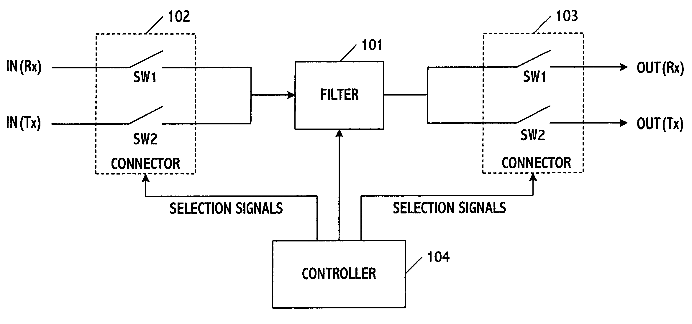
[0039] The present invention is a system and method for filtering signals in a communications transceiver. Unlike other approaches, the system and method use one filter or at least a portion thereof to process signals along the transmitter and receiver paths of the transceiver. This results in a substantial increase in processing speed and efficiency, and simultaneously a reduction in the size and cost of the chip incorporating the transceiver because less hardware is being used. Also, in order to optimize performance the filter characteristics may be varied based on whether transmitter or receiver signals are being processed, however the same filter characteristics may be used for both types of signals if desired. Also, while the filter is ideally suited for use in the front-end and more specifically the baseband signal recovery portion of the transceiver, those skilled in the art can appreciate that other locations are possible including the signal processing portion or any other ...


PUM


Abstract

A system and method for filtering signals in a communications system reduces hardware and chip size requirements by selectively connecting a filter along transmitter and receiver paths of a transceiver. In operation, a controller generated signals for connecting the filter along the transmitter path when the transceiver is in transmitter mode and for connecting the filter along the receiver path when the transmitter is in receiver mode. The controller then generates additional signals for setting one or more parameters of the filter based on the path connected, or put differently based on the operational mode of the transceiver. In a variation, the controller sets the parameters of additional elements coupled to the filter as a way of further controlling processing of the transmitter and receiver signals. The system and method are particularly well suited to controlling the filtering of signals at the front-end of the transceiver having a direct-conversion architecture and in general ones performing time-multiplexing applications.

Description

BACKGROUND OF THE INVENTION [0001] 1. Field of the Invention [0002] This invention generally relates to processing signals, and more particularly to a system and method for filtering signals in a transceiver of a communications system. [0003] 2. Description of the Related Art [0004] A transceiver is an integrated device which transmits and receives signals in a communications system. Transceivers generally operate in one of two modes. If the transceiver is unable to receive signals while transmitting, it is said to operate in half-duplex mode. If the transceiver is able to receive signals while transmitting, it is said to operate in full-duplex mode. Full-duplex mode transceivers make up the predominant share of all RF transceivers in use today, however half-duplex mode transceivers still perform many important applications. [0005] The receiver part of a transceiver includes a front-end portion and a signal-processing portion. The front-end portion performs the function of baseband ...

Claims


Application Information

Patent Timeline
CPCH04B1/1027H03H11/1252H04B1/44H03J1/0008H03H11/1291H04B1/40H04B1/16H04B1/48
Inventor JEON, YOUNG-DEUKLEE, SEUNG-WOOKLEE, JEONG-WOOPARK, JOONBAELEE, KYEONGHO
Owner GCT SEMICONDUCTOR INC
Why Eureka
Try Eureka