This helps you quickly interpret patents by identifying the three key elements:
Problems solved by technology
Method used
Benefits of technology
Benefits of technology
[0012] It is an objective of the present invention to minimize the time required to determine the location of a single bit error in a group of data bits. It is also an objective of the present invention to minimize the amount of circuitry required to determine the location of a single bit error in a group of data bits.
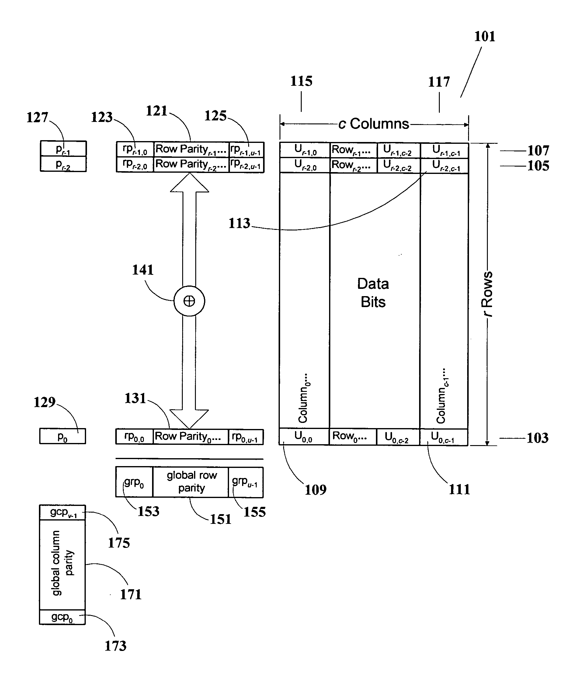
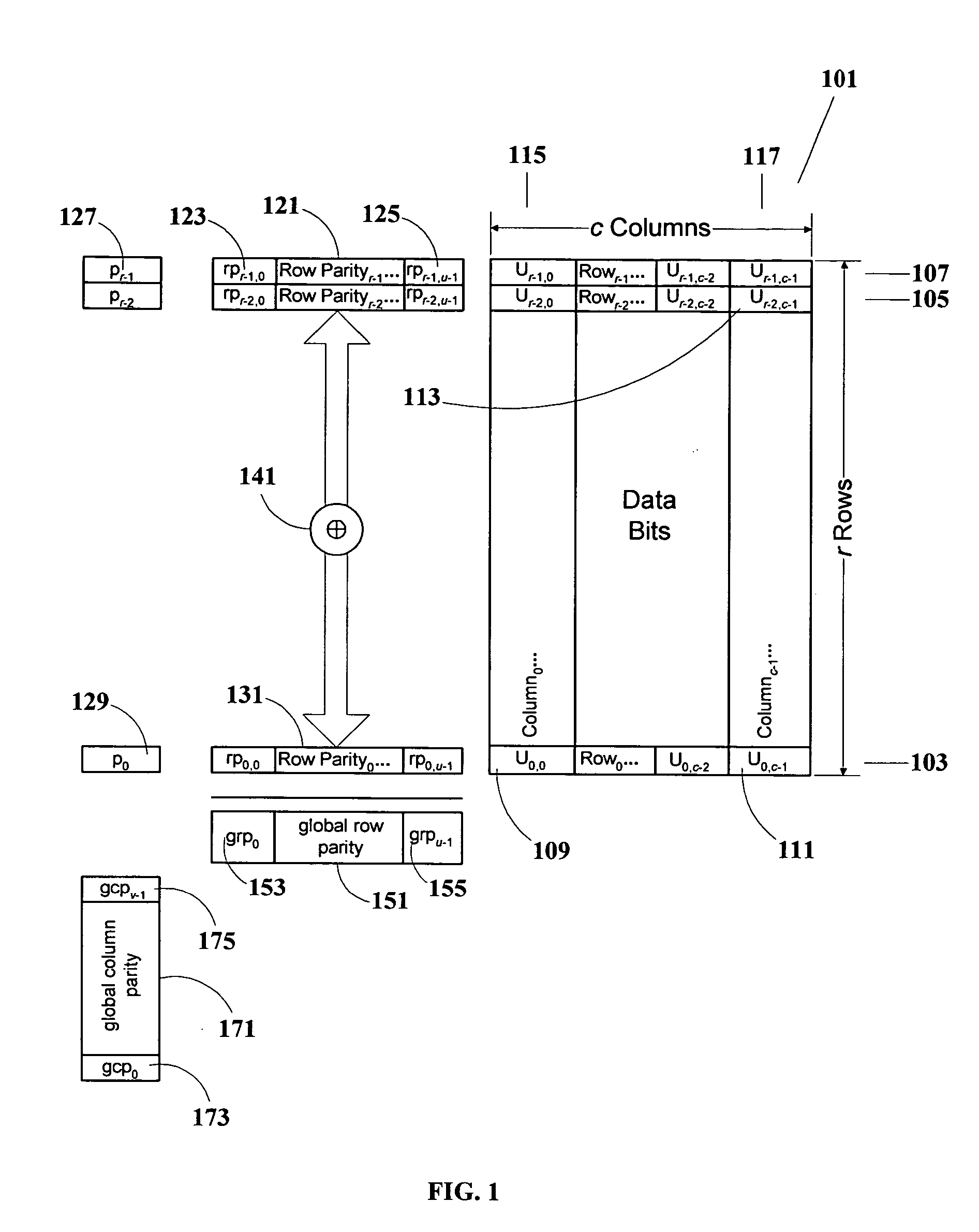
[0015] The last row of data in the data array can be incomplete, so that the number of data bits can be less than the product r*c. In addition, the scheme is optimized when r equals c, because the array is square and only a single table is needed, thereby further reducing the hardware requirements to the minimum. In general, instead of a table size of k*2k bits, the optimum table size according to the present invention is only k / 2*2k / 2. As a comparison with the example previously presented, instead of a 13-kilobyte lookup table, the present invention requires only 7*27=896 bits for the lookup table, less than a kilobyte, and requiring a small and easily-manageable hardware circuit, less than 7% of the size previously needed.
Problems solved by technology
Encoding and decoding according to strong forward error-correcting codes, however, must be done either in software or with complex circuitry.
Therefore, where there exist restrictions on the use of software or constraints on the size and complexity of hardware implementations, it may be necessary to use simpler error-detection and error-correction techniques.
As a non-limiting example of the above, data retrieval from a monolithic flash memory exhibits restrictions both on the use of error-correction decoding software and on the complexity of hardware error-correction decoder implementations.
At the time of device startup, software loading has not taken place, so decoding cannot be done in software.
Moreover, there are strict constraints on the complexity of the hardware circuitry which can be incorporated into the control logic of such devices.
The discrete logarithm problem is believed to be a difficult problem; there is no known general polynomial-time solution for this problem.
The Meggitt decoder typically has a low gate count, but requires a lot of time to perform the computations and thereby to obtain the error location.
This approach has the advantage of speed but is highly demanding of storage space.
This is a highly inefficient use of storage and logic space—a 13 kilobyte table is required for error-correcting half a kilobyte of data.
However, in the monolithic flash memory with integrated control logic, neither approach is satisfactory.
The result is that the control logic on the integrated chip is slow and of insufficient density to support standard decoding techniques.
Method used
Image
Click on the blue label to locate the original text in one second.
Reading with bidirectional positioning of images and text.
Examples
example 1
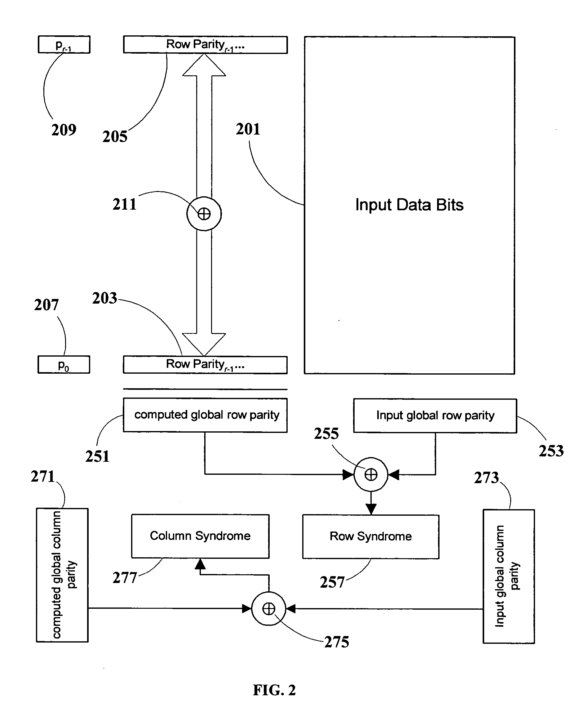
[0068] Let the correct value of all data bits be 0 (zero). In this case, input global row parity vector 253 (FIG. 2) is 0000000, and input global column parity vector 273 (FIG. 2) is also 0000000.
[0069] Now let there be an error in bit 57110, so that bit 57110 reads as 1 instead of 0. Using the conversion rules above: [0070] bit 57110 is in row 5510 (571 div 64=8; 63−8=55) [0071] bit 57110 is in column 410 (571 mod 64=59; 63−59=4)
[0072] With the exception of row 5510, whose computed row parity vector is 1001100, all individual computed row parity vectors are 0000000. Thus, computed global row parity vector 251 (FIG. 2) is 1001100=4 Ch, which is also the value of row syndrome 257 (FIG. 2).
[0073] Using Equation (9) above, it is seen that the decoded column error location is given by:
[0074] Next, the overall parity bits of each row will be 0 (zero) except P55, and thus computed global column parity vector 271 (FIG. 2) is 101...
example 2
[0077] In this example, arbitrary data is written and encoded, a portion of which is shown in Table 2. Note that the row and column locations as shown in Table 2 are numbered to take into account the parity vector bits. That is, the data columns are numbered starting at column 7, rather than column 0, and the data rows are numbered starting at row 7, rather than row 0. Furthermore, the data is ordered from MSB to LSB, so the bit strings of the derived row and column locations are backwards and have to reversed before using Table 1.
[0078] Also note that the data bit at column 34 and row 13 is written as a 0 (zero). This is the correct value for this data bit.
[0079] As previously described, each individual row parity vector is calculated by encoding a row of data. These individual row parity vectors are XORed together, and the result is encoded and saved as the global row parity vector. The overall parity bit is the 1 parity bit of each row, and these overall parity bits are encoded...
PUM
Abstract
A compact high-speed data encoder / decoder for single-bit forward error-correction, and methods for same. This is especially useful in situations where hardware and software complexity is restricted, such as in a monolithic flash memory controller during initial startup and software loading, where robust hardware and software error correction is not feasible, and where rapid decoding is important. The present invention arranges the data to be protected into a rectangular array and determines the location of a single bit error in terms of row and column positions. So doing greatly reduces the size of lookup tables for converting error syndromes to error locations, and allows fast error correction by a simple circuit with minimal hardware allocation. Use of square arrays reduces the hardware requirements even further.
Description
[0001] The present application claims benefit of U.S. Provisional Patent Application No. 60 / 534047 filed Dec. 30, 2003FIELD OF THE INVENTION [0002] The present invention relates to forward error-correcting encoding and decoding and, more particularly, to compact and efficient circuitry for single-bit error correction. BACKGROUND OF THE INVENTION [0003] In many cases requiring forward error correction, it is desired to use a robust error-correcting code, such as a BCH product code, to provide strong error correction capabilities. Well-known “forward error correction” techniques and codes supplement data intended for one-way transmissions with additional redundant data, to permit the receiver to detect and correct errors up to a predetermined number of errors. The term “forward error correction” is also applied herein to data storage, to permit the retriever of the stored data to detect and correct errors up to a predetermined number of errors. Encoding and decoding according to stron...
Claims
Application Information
Patent Timeline
Application Date:The date an application was filed.
Publication Date:The date a patent or application was officially published.
First Publication Date:The earliest publication date of a patent with the same application number.
Issue Date:Publication date of the patent grant document.
PCT Entry Date:The Entry date of PCT National Phase.
Estimated Expiry Date:The statutory expiry date of a patent right according to the Patent Law, and it is the longest term of protection that the patent right can achieve without the termination of the patent right due to other reasons(Term extension factor has been taken into account ).
Invalid Date:Actual expiry date is based on effective date or publication date of legal transaction data of invalid patent.

