
Network apparatus

a network apparatus and network technology, applied in the field of network apparatus, can solve the problems of user's terminal not being able to confirm on the user's terminal side, communication via wireless network cannot be established between the user's terminal and the to-be-managed device, and changing settings

Active Publication Date: 2005-03-03
BROTHER KOGYO KK
View PDF8 Cites 55 Cited by
  • Summary
  • Abstract
  • Description
  • Claims
  • Application Information

AI Technical Summary

Benefits of technology

[0017] With this network apparatus, when an instruction to execute or trial control to change over a target of communication from the first network apparatus to the second network apparatus is received from the user's terminal via the network, whether the device can operate properly after the execution of the control or not can be tested before the execution of the control, and information indicating the result of the testing can be reported to the user's terminal via the network in spite of the configuration in which the connection between the deice and the user's terminal will be cut if the control is executed. Accordingly, the user can confirm, on the user's terminal side, the information reported from the device, and if necessary, the user can carry out operation such as reviewing the contents of the second connection data so that the device can operate properly.
[0020] It is generally desired that the first storage unit is a nonvolatile storage in which the aforementioned connection data will not disappear even if power supply to the device is cut off. For example, the first storage unit may be formed out of a nonvolatile RAM (NVRAM) or a flash memory. When the first storage unit itself is a volatile storage, another nonvolatile storage may be used separately from the first storage unit so that data can be copied from the nonvolatile storage to the first storage unit. The second storage unit does not have to be a nonvolatile storage particularly when the test unit uses it. However, once settings in the device have been changed, the second connection data stored in the second storage unit have to be handled as new first connection data. Therefore, when the second storage unit is a volatile storage, it is desired that the second connection data are copied into the nonvolatile first storage unit and set as new first connection data. Alternatively, the first and second storage units may be formed as nonvolatile storages having one and the same configuration, while a flag indicating which storage to use as the first storage unit (or the second storage unit) is stored in a nonvolatile management region. In this case, the initial second storage unit itself can be handled directly as a new first storage unit only if the flag is rewritten. It is therefore possible to save the trouble of copying the second connection data into the nonvolatile first storage unit as described above.

Problems solved by technology

Assume that settings on the side of a to-be-managed device (router) are changed on the side of a user's terminal (host) connected though a network, and there is a problem in the changed settings.
In this case, therefore, there is a defect that the user cannot confirm on the user's terminal side whether the to-be-managed device after changing the settings is operating properly or not.
In such a case, communication via the wireless network cannot be established between the user's terminal and the to-be-managed device.
In this event, communication cannot be established between the user's terminal and the to-be-managed device.
Accordingly, the situations presented here by way of example lead to a problem that the user cannot confirm on the user's terminal side whether the to-be-managed device after changing the settings is operating properly or not.

Method used


Image

  • Network apparatus
  • Network apparatus
  • Network apparatus

Examples


first embodiment

[0047] [First Embodiment]

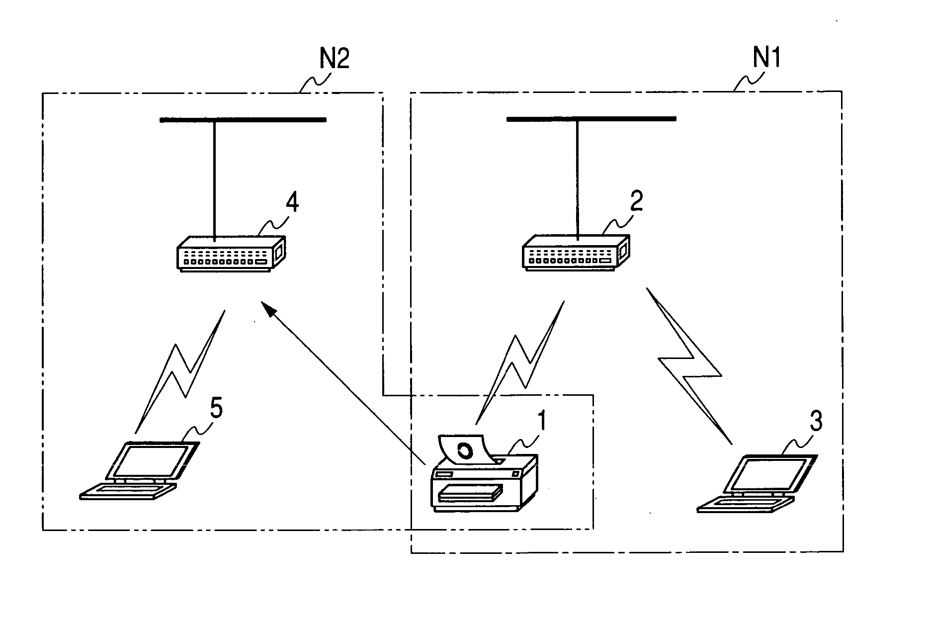
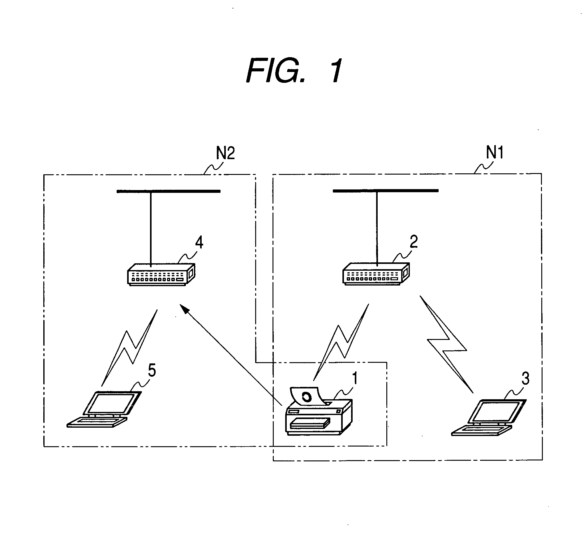
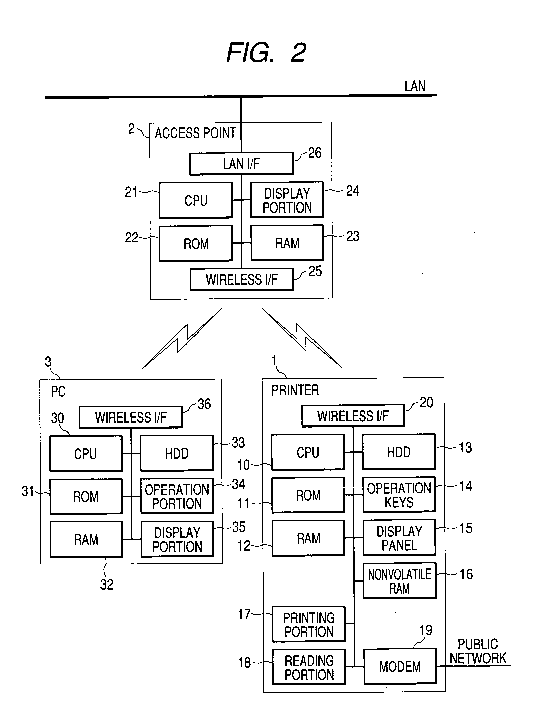
[0048] A network apparatus will be described below as a first embodiment of the invention. The network apparatus is a network printer (hereinafter referred to as “printer” simply) which can arrange a network using a wireless LAN system in conformity with IEEE 802.11 series standards and which is designed to receive print data transmitted from another network apparatus and print the print data. More in particular, the printer is designed to serve as a wireless terminal in an infrastructure system wireless network so as to establish wireless connection with a wireless access point. The print data are transmitted from the aforementioned other network apparatus to the printer via the wireless access point. The printer is also designed as a complex machine having an image scanner function, a facsimile function, a copying machine function, etc. as well as the aforementioned network printer function.

[0049]FIG. 1 is a diagram showing an example of a network in whic...

second embodiment

[0089] [Second Embodiment]

[0090] Next, description will be made on a second embodiment. A network apparatus which will be described as the second embodiment is a network printer similar to that in the first embodiment. Since the hardware configuration of the network printer is quite the same as that in the first embodiment, constituent members the same as those in the first embodiment are denoted by the same reference numerals correspondingly, and detailed description thereof will be omitted. The second embodiment is different from the first embodiment in a part of the process to be executed by the printer 1. The process to be executed by the printer 1 in the second embodiment will be described below with reference to the flow chart of FIG. 8. The process shown in FIG. 8 is a process to be executed by the printer 1 as soon as the power of the printer 1 is turned on.

[0091] When initiating the process, the printer 1 first operates in accordance with the settings in the NVRAM 16 (S302...

third embodiment

[0109] [Third Embodiment]

[0110] Next, a third embodiment will be described. A network apparatus which will be described as the third embodiment is also a network printer similar to that in the first or second embodiment. Since the hardware configuration of the network printer is quite the same as that in the first embodiment, constituent members the same as those in the first embodiment are denoted by the same reference numerals correspondingly, and detailed description thereof will be omitted.

[0111] The printer 1 according to the third embodiment can also arrange a network using a wireless LAN system in conformity with the IEEE 802.11 series standards in the same manner as in each embodiment described previously. The printer 1 is designed to serve as a wireless terminal in an infrastructure system wireless network so as to establish wireless connection with a wireless access point. In addition, though not referred to in each embodiment described previously, the printer 1 is also d...


PUM


Abstract

A network apparatus has a wireless communication unit wireless-communicating with a network apparatus, a connection control unit controlling the wireless communication unit based on connection data to establish connection with the network apparatus, a first storage unit storing first connection data for establishing connection with a first network apparatus, a second storage unit storing second connection data for establishing connection with a second network apparatus, a recording control unit recording the second connection data into the second storage unit when the connection control unit establishes connection with the first network apparatus, a test unit trying to establish connection with the second network apparatus when the connection control unit cuts off the connection with the first network apparatus after the recording control unit records the second connection data, and a return control unit re-establishing the connection with the first network apparatus after trying to establish connection with the second network apparatus.

Description

BACKGROUND OF THE INVENTION [0001] 1. Field of the Invention [0002] The present invention relates to a network apparatus which constructs a wireless network with other wireless access points or wireless terminals. [0003] 2. Description of the Related Art [0004] In recent years, when a user engaging in network management performs various managements (such as installation of software, maintenance with a change in settings, etc.), each network apparatus connected to a network such as a LAN (Local Area Network) has been often managed through the network not by use of an operation portion provided additionally in the network apparatus but by use of a terminal unit (hereinafter referred to as “user's terminal”) located on the same network from necessity of central control (the network apparatus to be managed from the user's terminal will be also referred to as “to-be-managed device”). [0005] Such a kind of remote management is obtained by management using SNMP (Simple Network Management P...

Claims


Application Information

Patent Timeline
Patent Type & Authority Applications(United States)
IPC IPC(8): G06F3/12H04L12/24H04L12/26H04L12/28H04W24/00H04W28/00H04W36/06H04W36/08H04W84/12H04W88/08
CPCH04L12/2697H04L41/0213H04L41/0806H04W84/12H04L43/50H04W24/00H04W36/08H04L41/0813
Inventor OHARA, KIYOTAKA
Owner BROTHER KOGYO KK
Learn More