Fistula blocker

Inactive Publication Date: 2005-03-03
NOVOMED
View PDF10 Cites 115 Cited by
  • Summary
  • Abstract
  • Description
  • Claims
  • Application Information

AI Technical Summary

Benefits of technology

[0028] It is proposed that the closure device have a semi-permeable porous surface structure running from cranial to caudal, preferably as membrane. In this way, substances such as pus and liquid can be led off from the fistula passage through the closure device from cranial to caudal while the penetration of impurities from the outside can be prevented.
[0029] The closure device can possibly have a spongy structure. This facilitates absorption and granulation of the closure device. With a spongy surface structure of the closure device, the body's own substances can easily penetrate the closure device and convert the latter or decompose it over a longer period of time.
[0030] As a variant of the invention, the closure device can be permeated with channels on the inside. This facilitates absorption of the closure device.
[0031] Advantageously, the cl

Problems solved by technology

In doing so, they frequently riddle the sphincter.
Due to transecting of the sphinc

Method used


Image

  • Fistula blocker
  • Fistula blocker
  • Fistula blocker

Examples


first embodiment

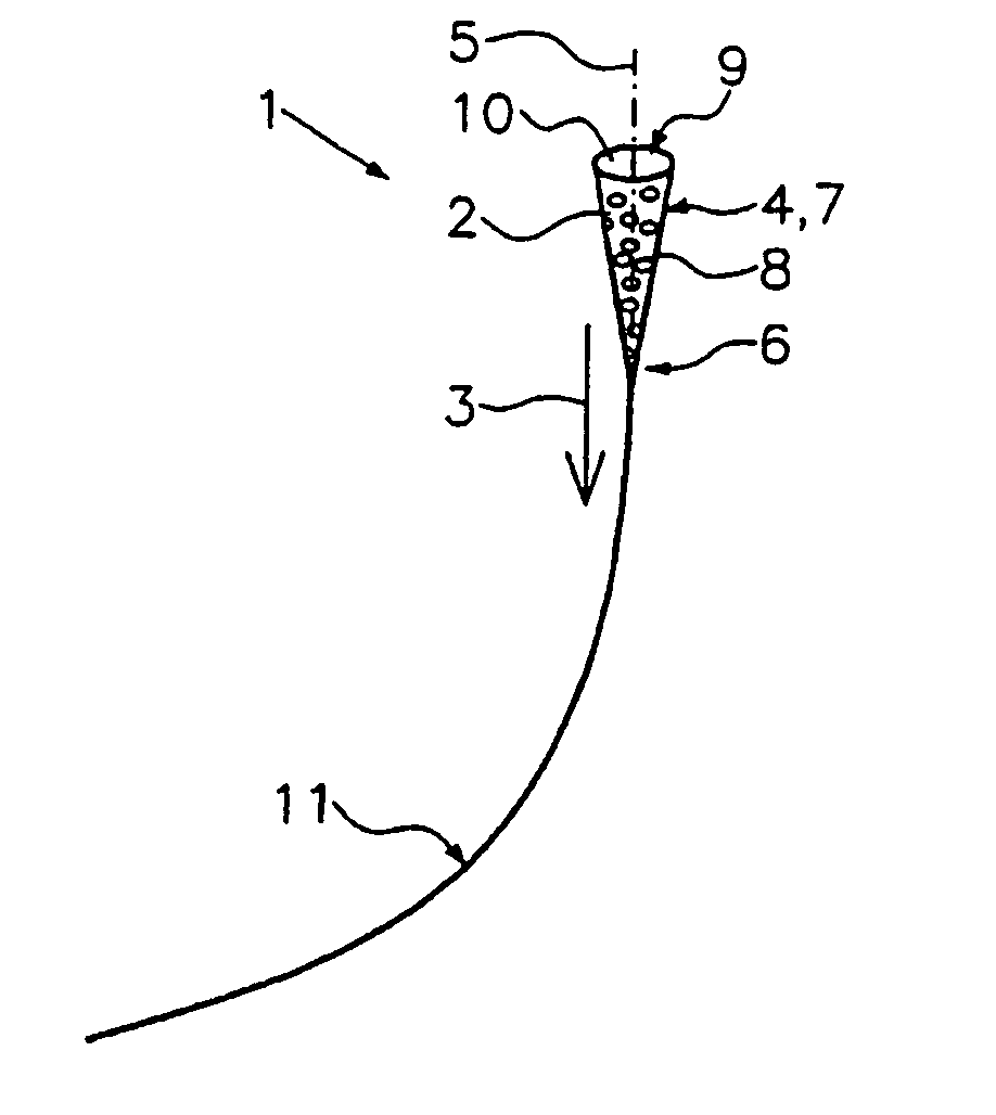
[0043] In FIG. 1, a fistula blocker 1 according to this invention for sanifying a fistula passage is shown. The fistula blocker has a plug-like closure device 2 which can be inserted into a fistula passage in the direction of insertion 3. The closure body 2 has a conical shape with a caudal thick end and a cranial thin end. The caudal end refers in this sense to the end contrary to the direction of insertion 3 while the cranial end is the end of the closure device 2 pointing in the direction of insertion 3.

[0044] The closure device 2 has a bearing surface 4 extending transverse to the direction of insertion 3 which is given with the conical shape by the surface of the cone's envelope. This surface is at least in places in contact with the wall of a fistula passage. The conical shape is rotationally symmetric to the longitudinal axis 5 of the closure device 2.

[0045] The cranial end of the closure device forms a guide section 6 and the caudal end of the closure device 2 forms a closi...

second embodiment

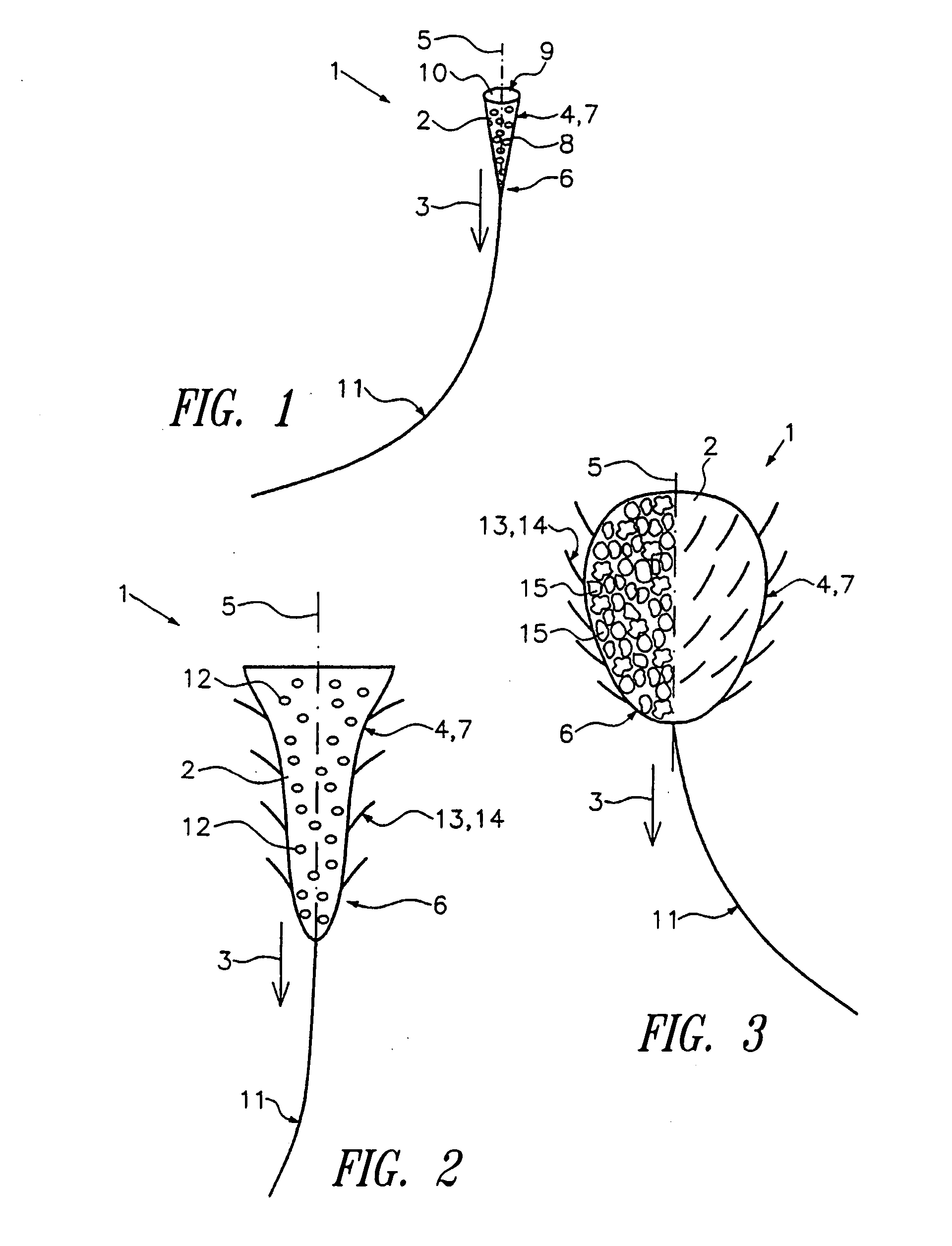
[0050] The closure device of the fistula blocker 1 has a closure section 7 with a concave outer shape expanding outward caudally. With the outer bearing surface 4 the fistula blocker 1 can get into contact with the fistula passage. The cranial guide section 6 of the closure device 2 has a shape which is arched somewhat convex forward and inwardly and which leads to the application string 11. In this way, the closure device 2 has somewhat of a bell shape longitudinally.

[0051] The closure device 2 is riddled on the inside with channels which via the channel openings 12 border on the outer surface of the closure device 2.

[0052] The closure device 2 is provided with an anchoring device 13 which has several barbed sections 14 distributed longitudinally to the girth and length of the closure device 2. The barbed sections 14 branch off laterally shored up from the closure device 2 and are aligned somewhat contrary to the direction of insertion 3. They are flexible to a limited extent.

third embodiment

[0053] In FIG. 3 a fistula blocker 1 according to the invention is shown. Identical reference symbols designate identical sections as in the details above so that in this regard reference can be made to the description above, unless something diverging from that is said below.

[0054] The closure device 2 has a somewhat egg-like shape the slimmer end of which is pointed in the direction of insertion 3. The closure device 2 has a spongy hollow structure which is illustrated in cross-section in the left half of the closure device 2. The spongy structure is shown in the form of several pores 15 which extend up to the outer surface of the closure device 2. The surface of the closure device 2 likewise has a correspondingly spongy structure. Accordingly, the closure device has a porous hollow structure inside.

[0055] In the right half, the closure device 2 is shown from the outside where for reasons of visibility the spongy structure has been deleted. On the outer side, the closure device 2...


PUM


Abstract

In order to create a treatment device for clearing up fistulas with which fistulas can be treated as sparingly as possible, and where the functions of the adjacent anatomical structures are to remain as intact as possible, the invention proposes a fistula blocker for clearing up a fistula passage with a plug-like closure device, at least somewhat insertable into a fistula passage, which has a bearing surface which extends at least in part circumferentially transverse to the direction of insertion and which can be brought into contact with the wall of a fistula passage, and where the closure device is provided with flexible application string which can be inserted into the fistula passage, the latter being designed as a drainage pipe.

Description

CROSS-REFERENCE TO RELATED APPLICATIONS [0001] This application is a continuation of U.S. patent application Ser. No. 10 / 009,242, filed Apr. 3, 2002 (now pending); which application is a U.S. National Phase Application of International Application No. PCT / EP00 / 05273, filed Jun. 7, 2000; which claims priority to German Patent Application No. 299 09 888.5, filed Jun. 7, 1999; all of which applications are incorporated herein by reference in their entireties.BACKGROUND OF THE INVENTION [0002] 1. Field of the Invention [0003] The invention refers to a fistula blocker to clear up a fistula passage, in particular for treatment of anal, bladder, intestinal and urogenital fistulas. [0004] 2. Description of Related Art [0005] Fistulas are tubular shaped tissue-lined connectors between body cavities or hollow organs amongst themselves or to the surface of the body. They frequently develop as a consequence of infections or accompany abscess formation. For example, anal fistulas arise primarily...

Claims


Application Information

Patent Timeline
IPC IPC(8): A61B17/00A61B17/03A61B17/12A61L31/00
CPCA61B17/0057A61B17/12022A61B17/12099A61B17/12159A61M27/00A61B2017/00641A61B2017/00654A61L31/00A61B17/12181
Inventor BURGARD, GUNTHER
Owner NOVOMED
Why Eureka
Try Eureka