Stent

a stent and stent technology, applied in the field of stents, can solve the problems of unacceptably high incidence of re-stenosis in patients treated by balloon angioplasty, adverse effects of narrowing of the vessel on blood flow through the vessel, and severely compromise the flow of blood to the “downstream” vessel. , to achieve the effect of preventing longitudinal movement of the stent in the vessel

Inactive Publication Date: 2005-03-03
COCKS GRAEME +1
View PDF13 Cites 139 Cited by
  • Summary
  • Abstract
  • Description
  • Claims
  • Application Information

AI Technical Summary

Benefits of technology

[0026] The tubular body may further include a transition region adjacent the at least first flange member. The transition region is preferably made up of a series of cells which have a small pore size relative to the cells of the at least first flange member and the remainder of the tubular body. In this embodiment, the transition region provides an area of relatively high expansile strength. In cases where the stent is used in ostial stenosis, which will be discussed further below, the transition region has the advantage of “pinning back” an area of stenosis around the ostium of a vessel.
[0081] The advantage of the delivery system of the sixth aspect is that the self expanding intraluminal stent may be delivered to a target site without the requirement of a bulky introducer catheter to hold the intraluminal stent in its first radially compressed state. In this regard, the compression member of the delivery system holds the intraluminal stent in its radially compressed state until the stent is advanced on the catheter to the target site.

Problems solved by technology

The resultant narrowing of the vessel has adverse effects on blood flow through the vessel.
In such cases, the plaque or area of stenosis may severely compromise the flow of blood to the “downstream” vessel.
Ostial stenosis may occur at the junction between the aorta and the renal artery and may predispose the patient to atheroembolisation of the visceral and peripheral vascular beds in addition to impairing blood flow to the kidney.
While both procedures are commonly used, the incidence of re-stenosis in patients treated by balloon angioplasty Is unacceptably high at an estimated 40% of cases.
The delivery of a stent to an ostial stenosis is a difficult procedure.
Similar difficulties are experienced with the placement of a stent in other regions of ostial stenosis in visceral vessels such as the mesenteric arteries and iliac arteries.

Method used


Image

  • Stent
  • Stent
  • Stent

Examples


Embodiment Construction

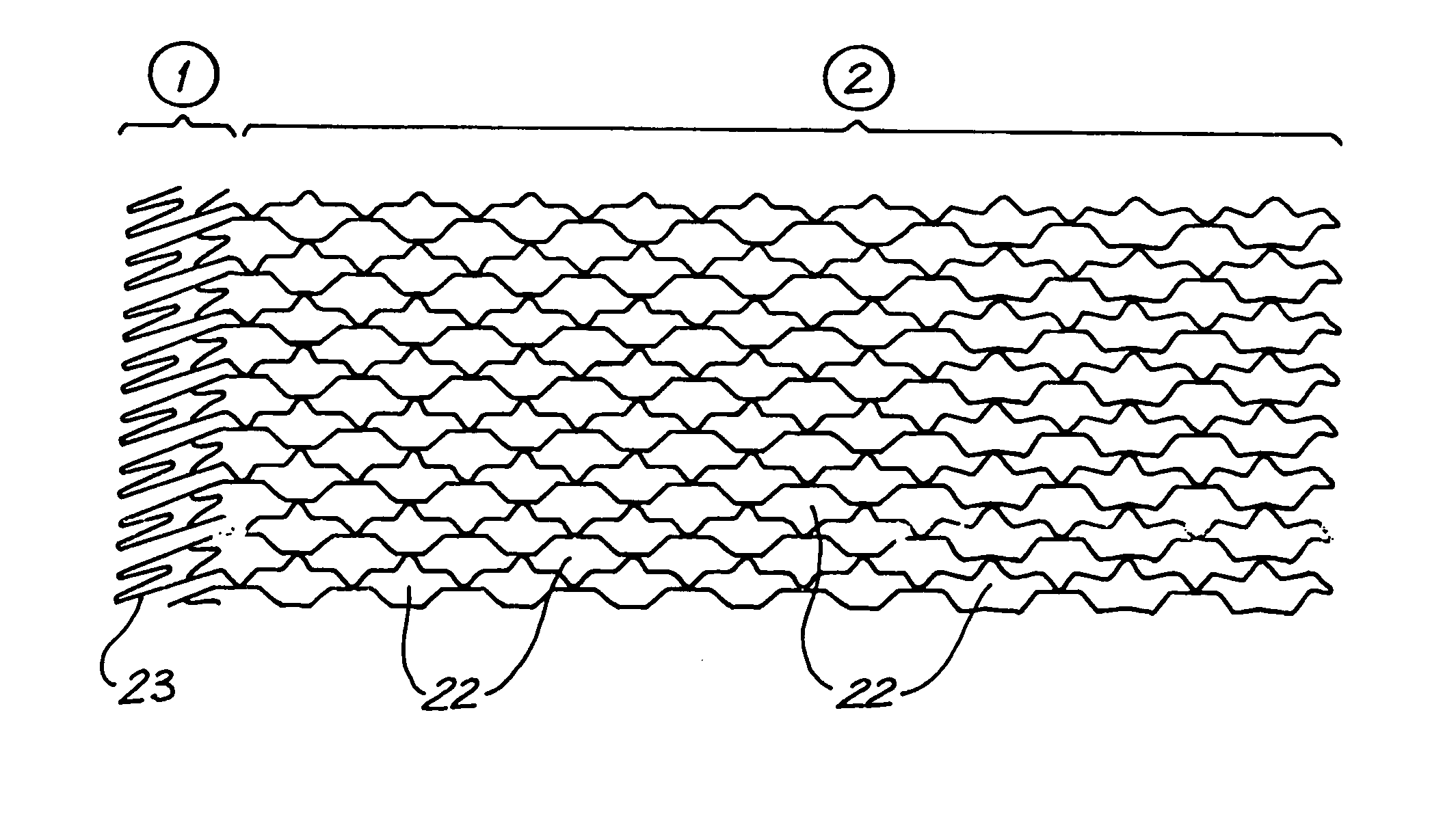
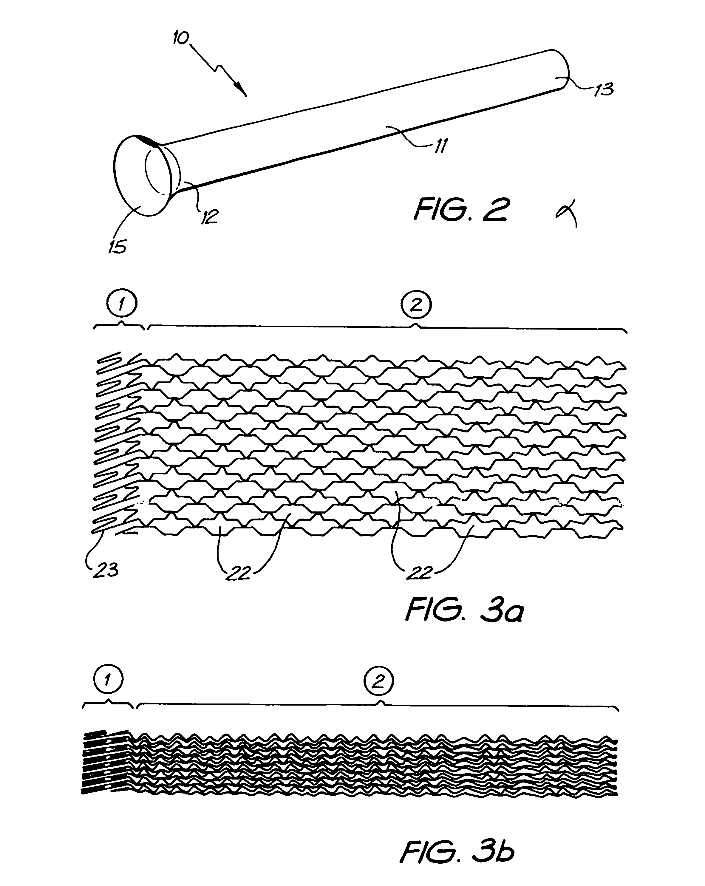
[0116] The intraluminal stent of the present invention is generally depicted as 10 in the accompanying drawings.

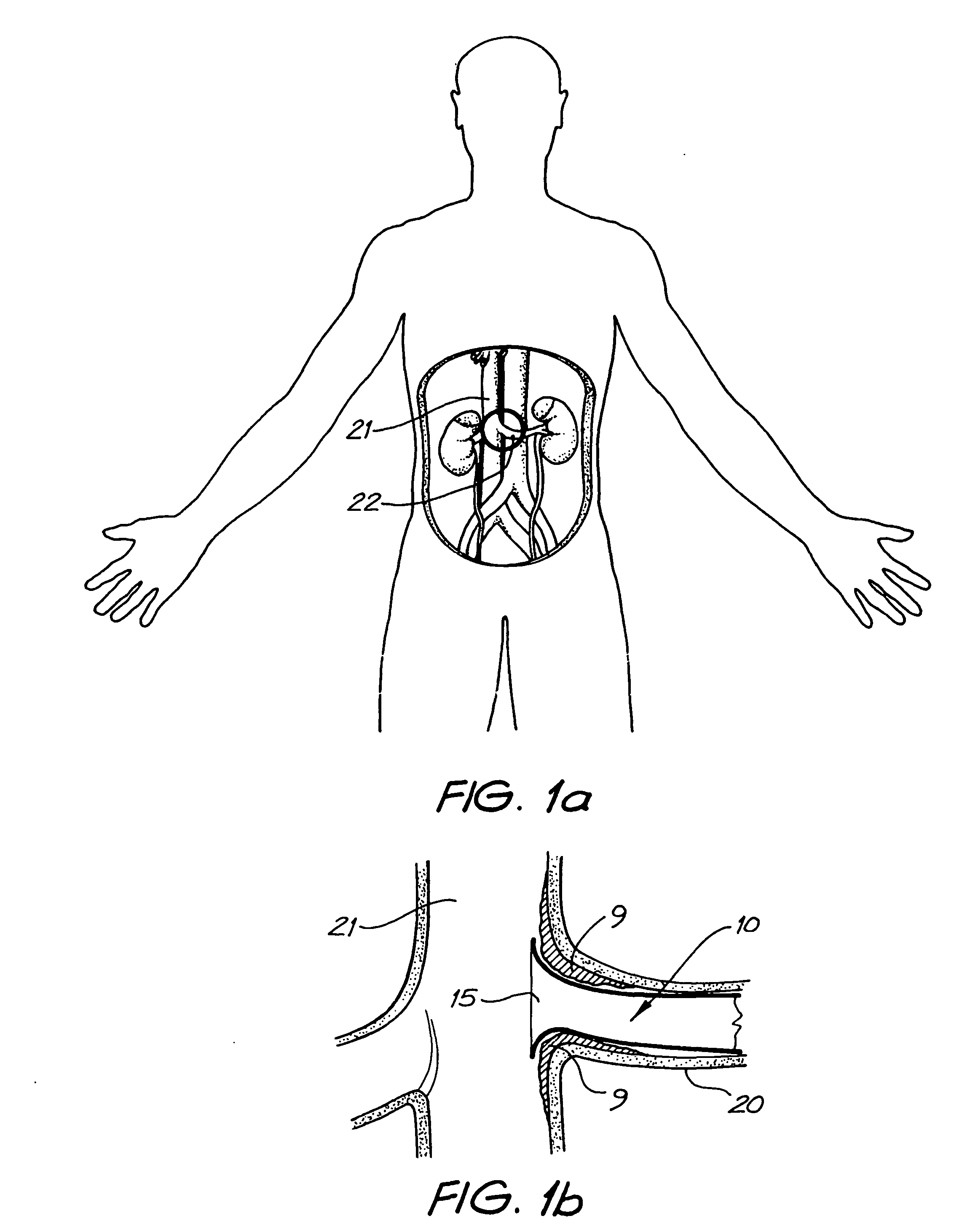
[0117] Preferably, the intraluminal stent of the present invention is used in the treatment of ostial stenosis although it is equally envisaged that it could be used in the treatment of any other form of stenosis. In ostial stenosis, the plaque or stenotic region 9 is formed at the junction between a pre-branching vessel 21 such as the aorta and a post-branching vessel 20 such as the renal artery which has the effect of narrowing the opening (ostium) of the post-branching vessel 20.

[0118] The intraluminal stent 10 comprises a tubular body 11 extending from a proximal end 12 to a distal end 13. The tubular body 11 is capable of expanding or being expanded from a radially compressed state (as depicted In FIGS. 3b, 5b and 7b) to a radially expanded state (as depicted in FIGS. 3a, 5a and 7a). When in the radially expanded state, the tubular body 11 includes a first flange me...


PUM


Abstract

A stent (10) which may be used in the treatment of stenosis and particularly ostial stenosis. The stent (10) includes a flange member (15) which engages the surrounding wall of an ostium and anchors the stent (10) in its target vessel. A delivery system for a stent (10) is also disclosed, the delivery system including a membrane (109) or a compression member to hold an intraluminal stent (101) in a first radially compressed state until said stent (101) is delivered to a target site.

Description

FIELD OF THE INVENTION [0001] The present invention relates to a stent for use in occlusive disease and particularly occlusive disease in an area of vessel which branches into a second vessel. BACKGROUND OF THE INVENTION [0002] Occlusive diseases affecting the vasculature or other vessels are common. Such diseases include atherosclerosis which is characterised by a build up of plaque from cholesterol residues. The plaque build up subsequently thickens and hardens the vessel wall to create a stenosis. The resultant narrowing of the vessel has adverse effects on blood flow through the vessel. [0003] Stenotic plaques may occur at any location along a vessel wall and in some cases may present at a junction between two vessels. This is commonly referred to as ostial stenosis or a narrowing of the opening of a vessel. In such cases, the plaque or area of stenosis may severely compromise the flow of blood to the “downstream” vessel. [0004] Many vessels branch from a main vessel at approxim...

Claims


Application Information

Patent Timeline
Patent Type & Authority Applications(United States)
IPC IPC(8): A61F2/00A61F2/82A61F2/91A61F2/915A61F2/958A61F2/962
CPCA61F2/91A61F2/915A61F2/958A61F2/962A61F2002/821A61F2230/0067A61F2002/91533A61F2002/9155A61F2002/91558A61F2250/0039A61F2002/91525
Inventor COCKS, GRAEMEWHITE, GEOFFREY H.
Owner COCKS GRAEME
Why Eureka
Try Eureka