
Distributed engine control system and method

a control system and engine technology, applied in the direction of machines/engines, process and machine control, instruments, etc., can solve the problems of limited redundancy of hierarchy control systems, lack of flexibility, and high cost of obsolescence concerns

Inactive Publication Date: 2005-03-03
GENERAL ELECTRIC CO
View PDF6 Cites 35 Cited by
  • Summary
  • Abstract
  • Description
  • Claims
  • Application Information

AI Technical Summary

Benefits of technology

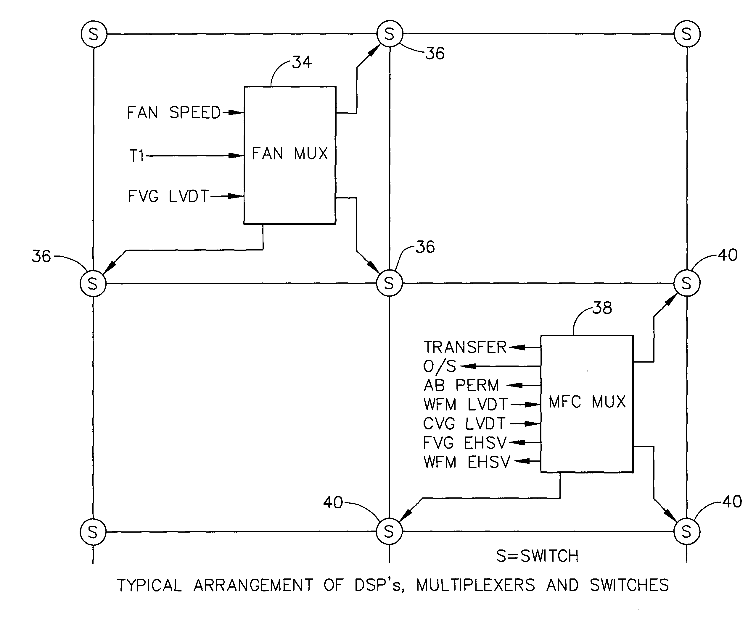
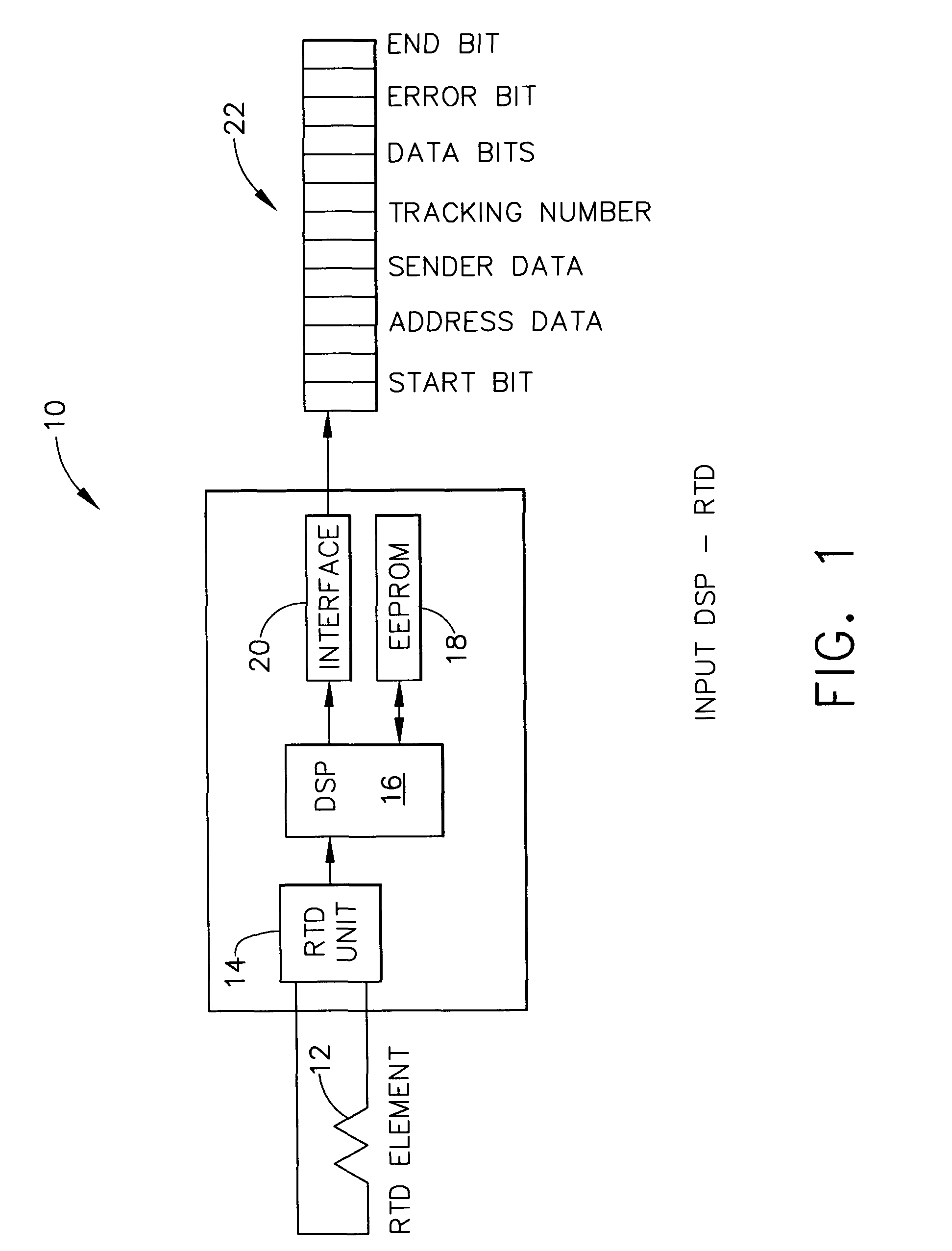
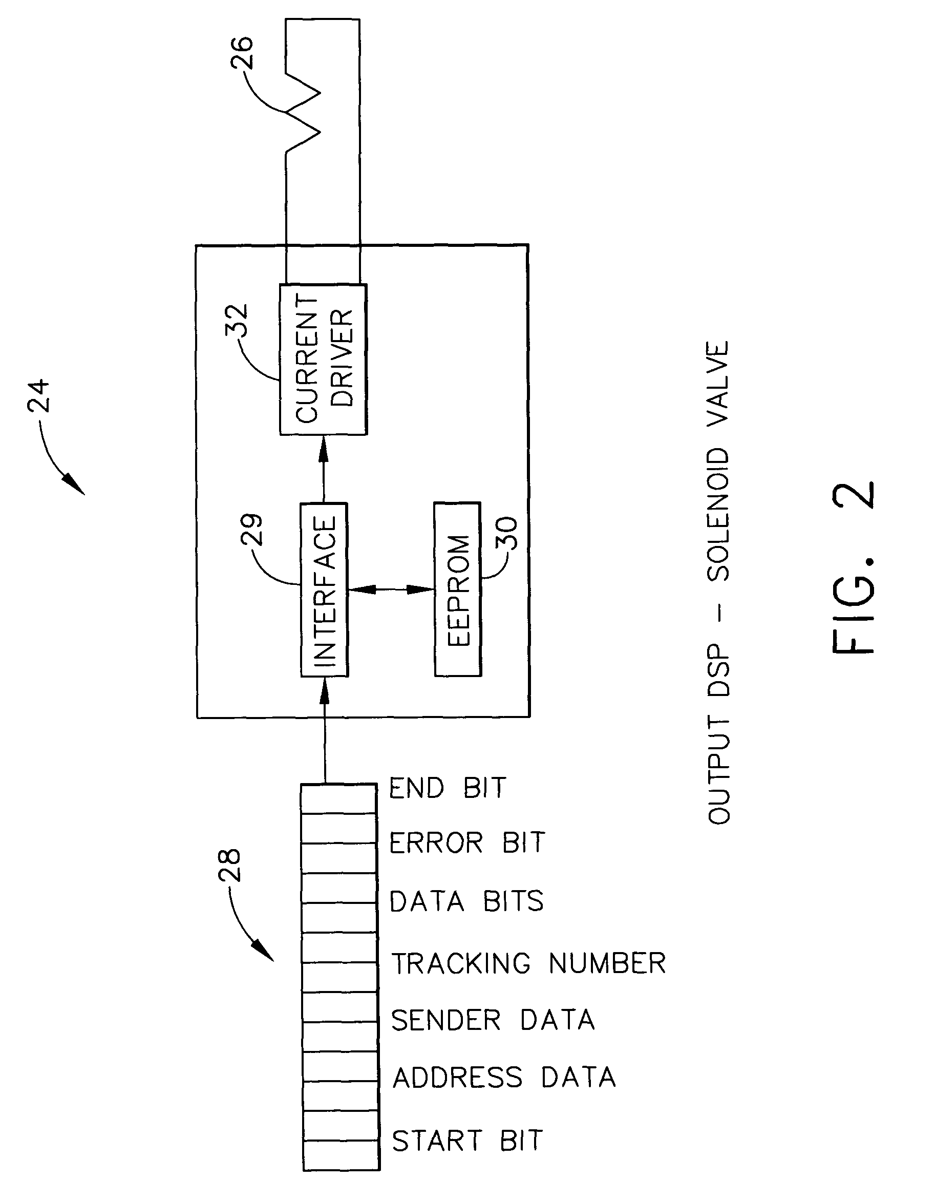
[0005] An architecture is proposed for allowing each control system element to locally and autonomously convert its analog information into digital data packets, or convert digital data packets into analog signals. While each sensor component still obtains measured data from its sensor elements, each sensor contains electronics to convert its data into digital data words.
[0006] Accordingly, the present invention provid...

Problems solved by technology

Hierarchical control systems have limited redundancy, lack flexibility, are subject to expensive obsolescence concerns, have extensive cabling requirements and have limited diagnostic capability.
Consequently, when the central processor unit for a channel fails, the functionality of that channel is lost.
A hierarchical control scheme leaves the entire system vulnerable to loss of all control channels.
The loss of multiple processors can result in loss of engine control.
While redundancy addresses many of the failure modes, it does not address all failure modes.
Furthermore, a significant design burden affecting cost, weight and complexity, is encountered in the current architecture at redundancy levels greater than dual.

Method used


Image

  • Distributed engine control system and method
  • Distributed engine control system and method
  • Distributed engine control system and method

Examples


Embodiment Construction

[0012] Modern gas turbine engine control systems typically consist of two fully capable, redundant, digital, electronic control system channels. Each control system channel has a full complement of sensors, signal processing electronics, control functions, and actuator drivers to assure safe, reliable engine operation throughout the aircraft flight envelope.

[0013] Current engine control systems incorporate analog input and output signals wired directly to the Full Authority Digital Engine Control (FADEC). FIG. 1 shows the configuration of a typical sensing unit 10 for the autonomous digital control system. Real time analog sensor data is acquired using a traditional sensing transducer, such as by measuring temperature via a resistive temperature device 12, applied to a sensing unit 14. The same principal would apply for any physical transducer. Electronics in the sensor would autonomously convert the analog signals into a stream of digital data words, as shown in FIG. 1. The digita...


PUM


Abstract

The present invention provides a system and method for safety critical real time distributed engine control. Centralized hierarchical control architecture is replaced with an autonomous distributed network. Analog input / output signals are replaced with digitized data packets. Point-to-point wiring and data bus control are replaced with flexible virtual connections using digital switching technology. Fixed redundancy is replaced with variable redundancy.

Description

BACKGROUND OF THE INVENTION [0001] The present invention relates to distributed control systems and, more particularly, to an autonomous distributed network for engine control. [0002] Hierarchical control systems have limited redundancy, lack flexibility, are subject to expensive obsolescence concerns, have extensive cabling requirements and have limited diagnostic capability. Transition from hard wired hierarchical systems to distributed systems has been ongoing within the voice, data, and video communication industry for several decades. These advancements have resulted in order of magnitude increases in bandwidth, major cost reductions and increased quality. While the technical concepts have been applied to some industrial control applications, current engine control systems still utilize hierarchical control architecture. System reliability is achieved by incorporating redundant control channels. Processing functions for each channel are controlled by the processors for that cha...

Claims


Application Information

Patent Timeline
IPC IPC(8): F02C9/28G05B9/03G06F19/00
CPCF02C9/28Y10T477/40G05B9/03
Inventor MOONEY, THOMAS D.
Owner GENERAL ELECTRIC CO
Learn More