
Shearing method for thin plate

a thin plate and shearing method technology, applied in the direction of metal working apparatus, etc., can solve the problems of increasing the cost of producing the spacer, reducing the production cost, and not achieving the accuracy of the prescribing, so as to reduce the cost, ensure the required flatness, and shorten the manufacturing steps

Active Publication Date: 2005-03-10
NAKAMURA IND MFG CO LTD
View PDF5 Cites 21 Cited by
  • Summary
  • Abstract
  • Description
  • Claims
  • Application Information

AI Technical Summary

Benefits of technology

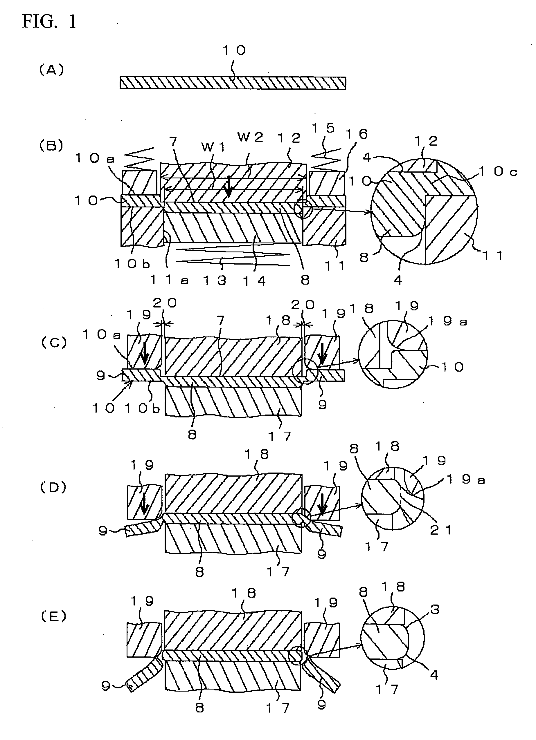
The present invention provides a shearing method for a thin plate that can prevent the formation of burrs and reduce the manufacturing steps and cost. The method involves performing half die cutting on the thin plate and then using a pressure punch to bend the scrap part around the product part and separate it from the product part. The method also includes forming a first sagging part on the one face side of the thin plate and a second sagging part at the edge portion of the product part. The technical effects of this invention include reducing burr formation, simplifying the manufacturing process, and improving the quality of the thin plate.

Problems solved by technology

However, individual component has a variation due to material itself and machining and thus, when the individual part is assembled or joined, a prescribed accuracy is not attained due to the accumulated error.
However, the etching processing requires a long producing time and thus increases the cost for producing the spacer.
Further, many spacers may not be used, which causes to increase the cost higher.
However, the method described above is not suitable to a plate whose thickness is less than about 0.5 mm.

Method used


Image

  • Shearing method for thin plate
  • Shearing method for thin plate
  • Shearing method for thin plate

Examples


Embodiment Construction

[0031] Shearing methods for a thin plate in accordance with preferred embodiments of the present invention will be described in detail below with reference to the accompanying drawings.

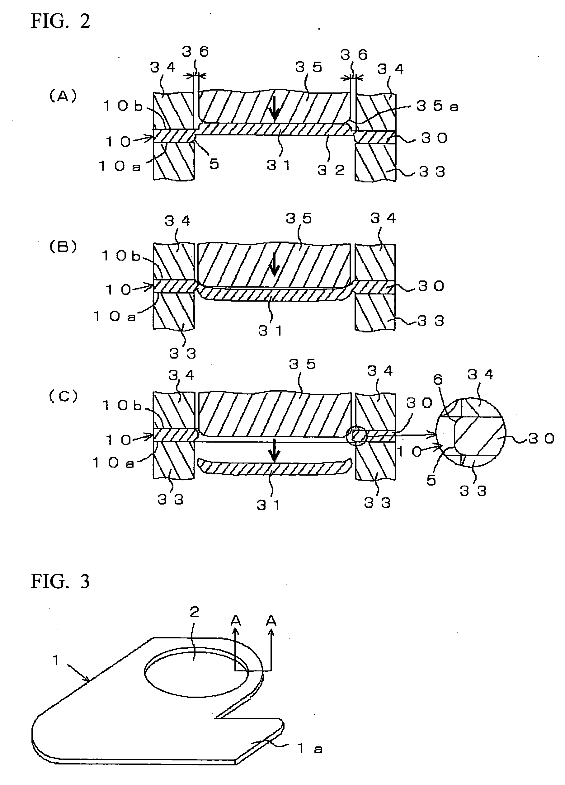
[0032]FIG. 3 shows a spacer 1 whose thickness is not more than 0.3 mm, which is shown as an example of a product which is manufactured by a shearing method for a thin plate in accordance with an embodiment of the present invention. The spacer 1 is a metal plate composed of a pure metal or alloy such as stainless steel, iron, aluminum, copper and brass, which is capable of plastic working and has a flatness required as a spacer used between the components shown in FIG. 7. Furthermore, the spacer 1 shown in the drawing has a thickness required to interpose between the components 100 and 101 shown in FIG. 7 and the planar shape of the spacer 1 is formed in a roughly “L”-shape. A circular through hole 2 is formed inside of the spacer 1.

[0033] The spacer 1 is formed, as shown in FIG. 4 which is the A-A s...


PUM

PropertyMeasurementUnit
thicknessaaaaaaaaaa
thicknessaaaaaaaaaa
thicknessaaaaaaaaaa

Abstract

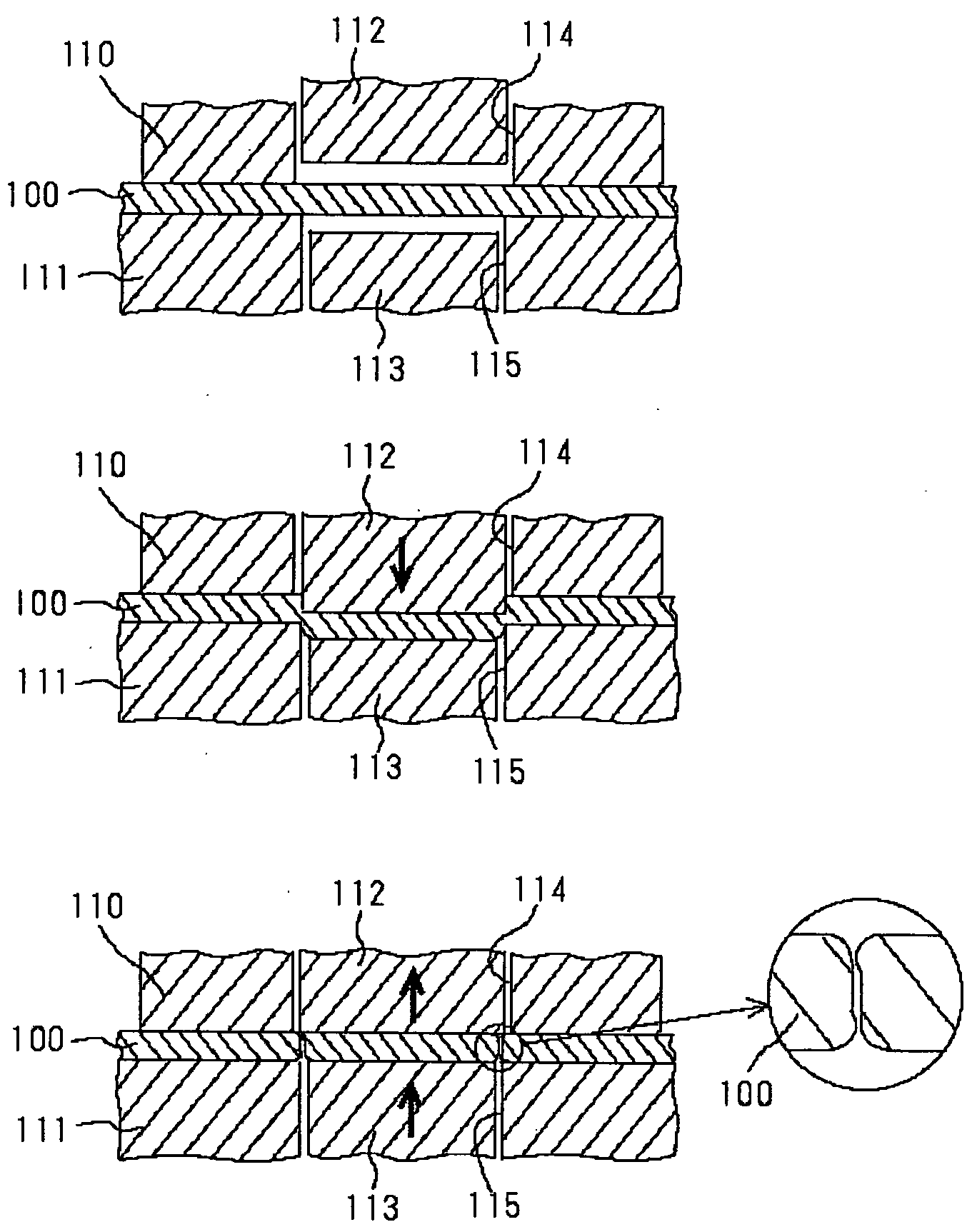
A shearing method for a thin plate including forming a protruded product part having a first sagging part when the thin plate with a thickness of not more than approximately 0.3 mm is performed with a half die cutting by pressing the half die cutting punch slightly larger than the half die cutting hole to form a shallow recessed part, fixing the product part by a fixing member, forming a second sagging part at an edge portion of the thin plate by pressurizing a scrap part by moving a pressure punch which is provided with a gap between the fixing member and the pressure punch and by being bent between the scrap part and the product part, and then separating the scrap part from the product part.

Description

BACKGROUND OF THE INVENTION [0001] 1. Field of the Invention [0002] The present invention relates to a shearing method for a thin plate in which a product part such as a spacer composed of a thin plate, for example, with the thickness of not more than approximately 0.3 mm is formed by shearing. [0003] 2. Description of the Related Art [0004] When various types of devices are assembled or some components are joined, the height, width or length with a high degree of accuracy is sometimes required. However, individual component has a variation due to material itself and machining and thus, when the individual part is assembled or joined, a prescribed accuracy is not attained due to the accumulated error. Therefore, as shown in FIG. 7, in order to correct the accumulated error, adjustment work is performed such that a spacer 102 composed of a thin plate is interposed between parts 100 and 101 to obtain a specified dimension. The accumulated error is individually different according to a...

Claims


Application Information

Patent Timeline
Patent Type & Authority Applications(United States)
IPC IPC(8): B21D28/16B21D28/10B21D28/18
CPCB21D28/18Y10T83/06
Inventor MIYAHARA, HIDEYUKI
Owner NAKAMURA IND MFG CO LTD
Learn More