Method for controlling a valve for an exhaust system

a technology of exhaust system and valve, which is applied in the direction of fluid pressure control, lighting and heating apparatus, instruments, etc., can solve the problems of reducing the heating performance of the heating system, pressure drop, and uncomfortable for the occupants of the vehicle, so as to reduce the pressure drop and reduce the pressure drop across the heat exchanger system

Active Publication Date: 2005-03-10
ET US HLDG
View PDF8 Cites 105 Cited by
  • Summary
  • Abstract
  • Description
  • Claims
  • Application Information

AI Technical Summary

Benefits of technology

[0007] To this end, the invention provides a method for controlling a valve in an exhaust gas heat exchanger system of a combustion engine. The exhaust gas heat exchanger system has a bypass duct and a heat exchanger duct with a heat exchanger. The method comprises the steps of determining that heat is to be transferred from exhaust gas flowing through the exhaust system to the heat exchanger. Thereupon, the valve is switched into a first position in which all of the exhaust gas flows through the heat exchanger duct. A pressure drop across the exhaust gas heat exchanger system is monitored either directly or indirectly. If the pressure drop reach...

Problems solved by technology

This results in a reduced heating performance of the heating system, which may be uncomfortable to a vehicle's occupants.
In general, a heat exchanger offers additional resistance to the exhaust gas flowing through the exhaust system, leading to a pressure drop.
Under some conditi...

Method used


Image

  • Method for controlling a valve for an exhaust system
  • Method for controlling a valve for an exhaust system
  • Method for controlling a valve for an exhaust system

Examples


Embodiment Construction

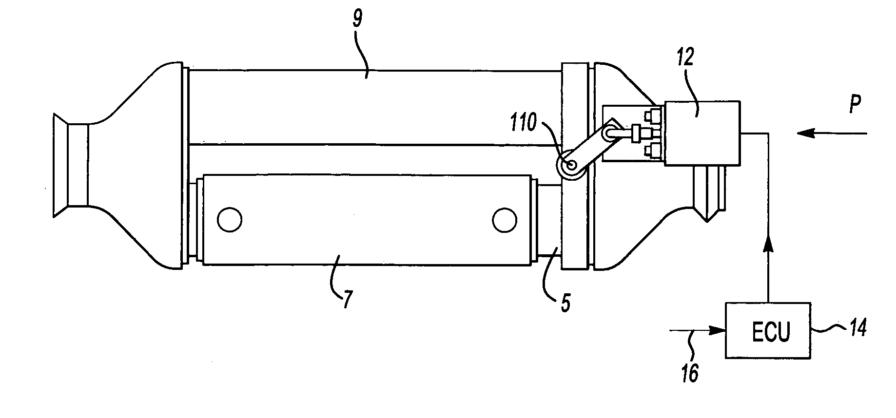
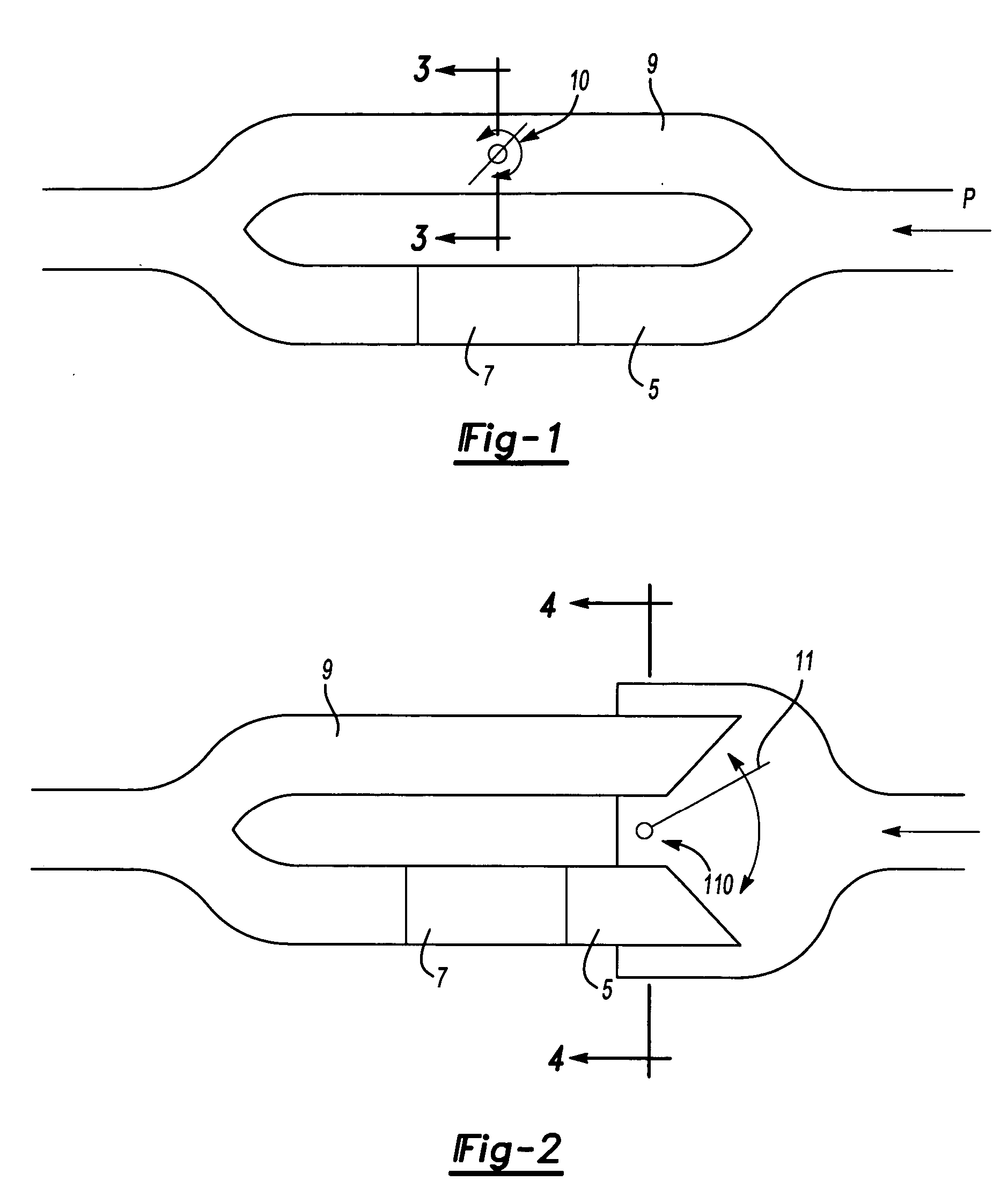
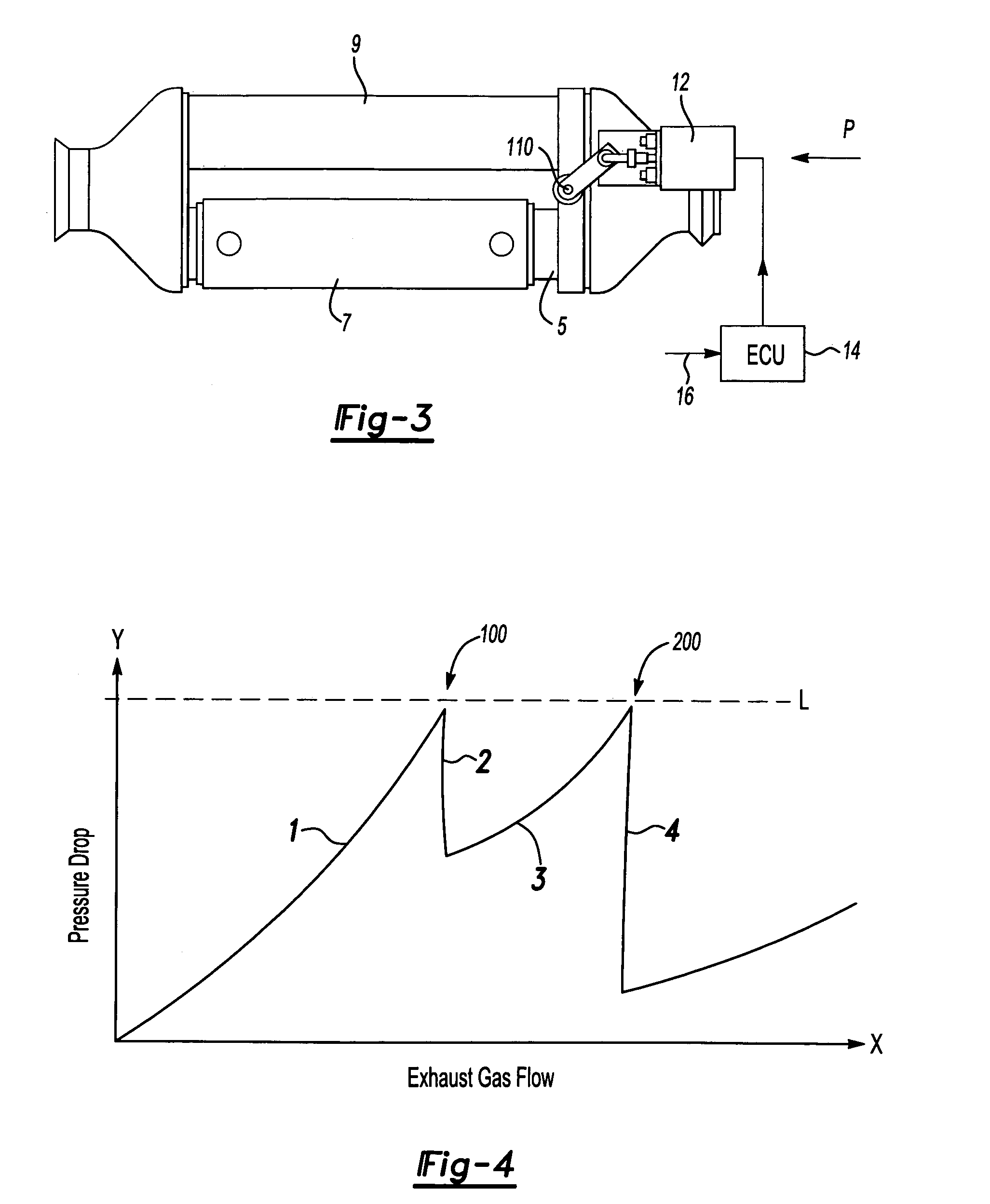
[0015] Two embodiments of heat exchanger units employed in auxiliary heating systems are now described with reference to FIGS. 1 and 2. In both systems, the exhaust gas of a combustion engine (not depicted) enters in the direction of arrow P from the right side with respect to the drawings. The system has a heat exchanger duct 5 with a heat exchanger 7 for the exhaust gas, and a bypass duct 9. A valve 10 is used to control the flow of the exhaust gas through heat exchanger duct 5 and bypass duct 9.

[0016] In the embodiment of FIG. 1, the proportion of the gas flow through the ducts is controlled by varying the flow resistance of bypass duct 9. When valve 10 is in a completely opened position, the flow resistance of bypass duct 9 is significantly less than the flow resistance of heat exchanger 7 in heat exchanger duct 5, resulting in almost no gas flow through the heat exchanger 7. When valve 10 is in a completely closed position, the gas flow through bypass duct 9 is blocked, and th...


PUM


Abstract

An exhaust gas heat exchanger system of a combustion engine has a bypass duct and a heat exchanger duct with a heat exchanger. A valve is controlled by determining when heat is to be transferred from exhaust gas flowing through the exhaust system to the heat exchanger. When heat is to be transferred, the valve is switched into a first position in which all of the exhaust gas flows through the heat exchanger duct. A pressure drop across the heat exchanger system is monitored either directly or indirectly. If the pressure drop reaches a predefined limit, the valve is switched into an intermediate position, resulting in a smaller portion of the exhaust gas flowing through the heat exchanger duct than when the valve is in the first position and a remaining portion flowing through the bypass duct, thereby reducing the pressure drop across the heat exchanger system. If the pressure drop again reaches a predefined limit, the valve is switched into a second position, resulting in an even smaller portion of the exhaust gas flowing through the heat exchanger duct, thereby further reducing the pressure drop across the heat exchanger system.

Description

[0001] This Nonprovisional Patent Application claims priority to U.S. Provisional Patent Application No. 60 / 500,587 filed on Sep. 5, 2003.BACKGROUND OF THE INVENTION [0002] The invention relates to a method for controlling a valve for an exhaust system of a vehicle, and in particular a valve used for controlling the flow of exhaust gas through a heat exchanger. [0003] A heat exchanger is part of auxiliary heating systems, which are increasingly used in vehicles having modern combustion engines with low fuel consumption. These combustion high efficiency engines produce, only a small amount of lost heat that is available for the heating system for the vehicle. This results in a reduced heating performance of the heating system, which may be uncomfortable to a vehicle's occupants. Accordingly, auxiliary heating systems have been developed that use a heat exchanger located in the exhaust system of the vehicle. The heat exchanger allows a gain of a certain portion of the heat of the exha...

Claims


Application Information

Patent Timeline
IPC IPC(8): B60H1/18F01N5/02F01N13/08F28F27/02
CPCB60H1/18F01N5/02Y02T10/16F01N2410/00F01N2410/10F01N13/087Y02T10/12
Inventor SPEER, GREGG
Owner ET US HLDG
Why Eureka
Try Eureka