
Structural knee bolster

a bolster and structural technology, applied in the direction of superstructure subunits, monocoque constructions, vehicle bodies, etc., can solve the problems of complex and expensive structure manufacturing, less strength of injection molding parts that might otherwise be available, and relatively complicated bolsters applied to the steering wheel area of cars. , to achieve the effect of sufficient strength

Active Publication Date: 2005-03-10
ABC GROUP
View PDF17 Cites 38 Cited by
  • Summary
  • Abstract
  • Description
  • Claims
  • Application Information

AI Technical Summary

Benefits of technology

[0011] In accordance with a first aspect of this invention, a bolster for assembly to an instrument panel assembly of an automobile vehicle includes a blow-molded component, the blow molded component having a generally aft wall and a generally forward wall. The bolster has first and second bolster transfer surfaces and a plurality of generally horizontally extending rib structures, the rib structures extending from adjacent the first bolster transfer surface to adjacent the second bolster transfer surface so that forces applied to the aft wall of the bolster in a location other than directly aft of said first and second bolster transfer surfaces, may be transferred through said bolster to said bolster transfer surfaces. The bolster has sufficient strength to prevent a substantial deformation of the bolster about a generally vertical plane when the bolster is subjected to a standardized force.

Problems solved by technology

Bending of the bolster about a vertical plane may then result in some of the instrument panel structure, including the bolster itself, infringing on the space envelope allowed for the steering column structure.
In the existing design envelope, bolsters applied to the steering wheel area of cars are relatively complicated structures comprising a bolster as well as the steering column protector.
However, due to the very nature of injection molding, parts made by the injection molding process often have less strength that might otherwise be available from the plastic resins used in the injection molding process.
While this is a complicated and expensive structure to manufacture, there is also the question of what happens if the driver's knees are not located directly aft of the energy absorption structure.

Method used


Image

  • Structural knee bolster
  • Structural knee bolster
  • Structural knee bolster

Examples


Embodiment Construction

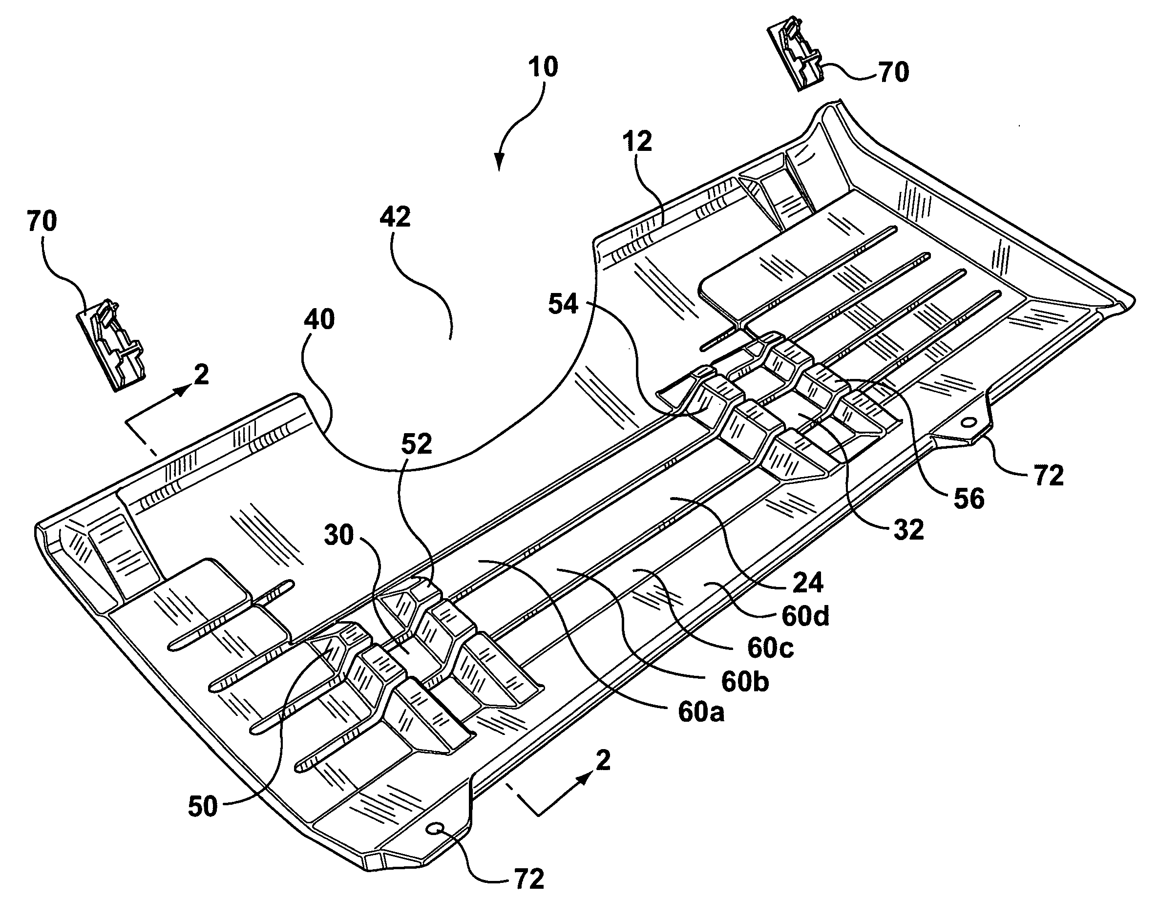
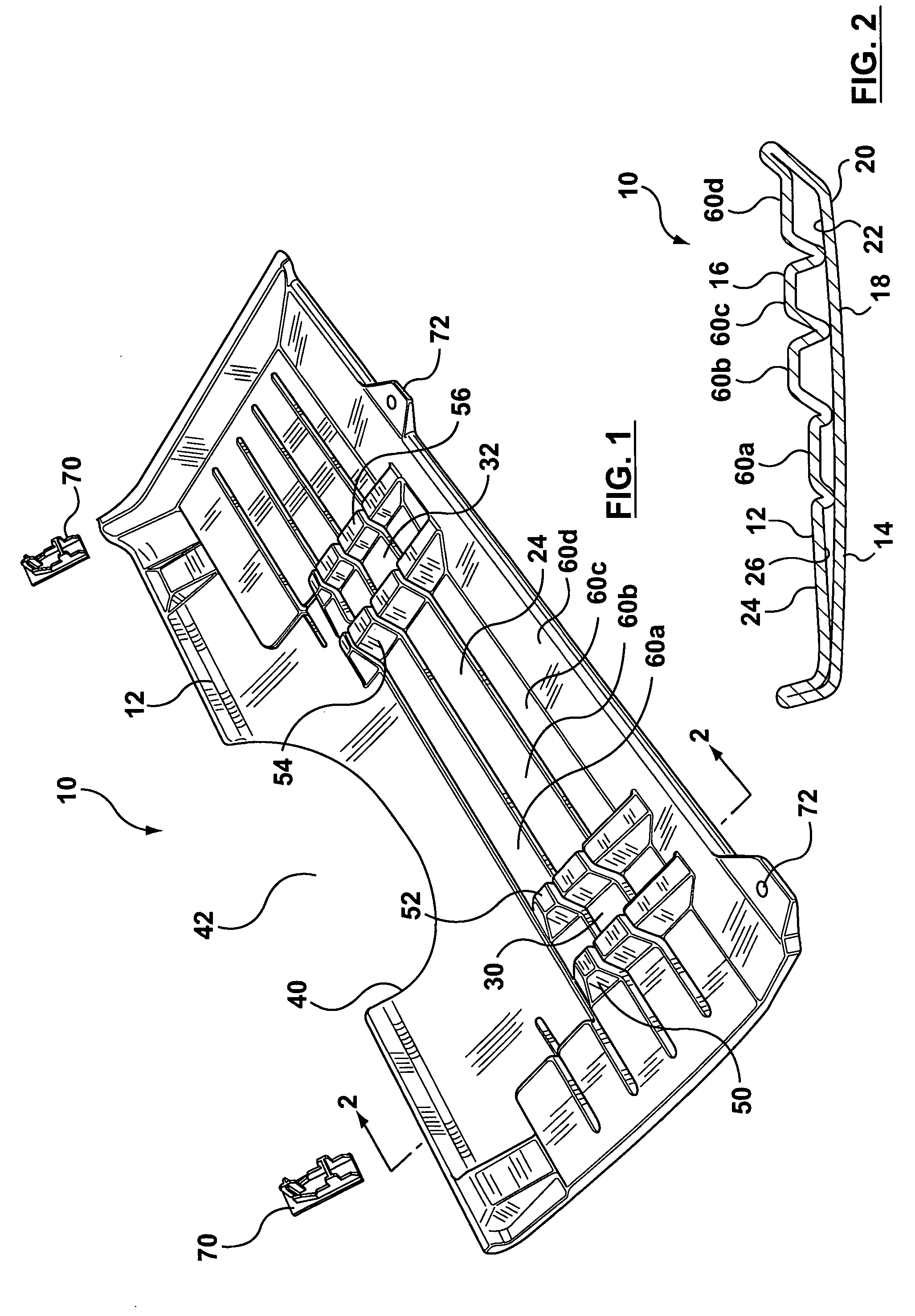
[0026]FIG. 1 illustrates a one-piece bolster 10. The bolster 10 has a forward facing surface 12 and an aft facing surface 14. The directions fore and aft or rearward and forward are used throughout this disclosure to refer to directions within the vehicle. The aft facing surface of the bolster is visible within the drivers compartment of the vehicle with the forward surface facing toward the front bumper, a surface which is not generally visible from within the vehicle. It will be understood that a bolster is typically a curved structure rather than planar, thus throughout this disclosure the surfaces and walls are referred to as generally aft and generally forward.

[0027] By reference to FIG. 2, it will be noted that the bolster 10 is a hollow structure having a forward wall 16 and an aft wall 18. The aft wall 18 has an aft surface 20 and an internal rear wall surface 22. The forward wall 16 has a forward surface 24 and an internal forward wall surface 26.

[0028] The bolster 10 inc...


PUM


Abstract

A bolster for assembly to an instrument panel assembly of an automotive vehicle is provided. The vehicle has a steering column with a steering column axis and at least two energy absorbing brackets located laterally to either side of the steering column axis. The bolster comprises a unitary structure having a generally forward wall and a generally aft wall. The forward wall has a forward wall, forward surface. The forward wall, forward surface includes first and second bolster transfer surfaces for transferring forces from the bolster to the energy absorbing brackets. The bolster further comprises a plurality of generally laterally extending rib structures. The rib structures extend from adjacent the first bolster transfer surface to adjacent the second bolster transfer surface. The plurality of generally laterally extending ribs structures have sufficient strength to inhibit bending of the bolster about a vertical plane when struck by a driver's knees at a point or points that are not directly aft of the bolster transfer surfaces, when the force is equal to or less than an amount specified by a test standard.

Description

CROSS-REFERENCE TO RELATED APPLICATIONS [0001] This application claims benefit from U.S. provisional application Ser. No. 60 / 500,446 filed Sep. 5, 2003, which is incorporated herein by reference in its entirety.FIELD OF THE INVENTION [0002] The invention relates to bolsters for an instrument panel for an automotive vehicle and more particularly to a bolster which is located adjacent the steering column of the vehicle. BACKGROUND OF THE INVENTION [0003] In the manufacture of automotive vehicles such as passenger cars and trucks, there are many safety standards that must be met by the vehicle to reduce the likelihood and / or severity of injury to occupants during an accident. [0004] For example, in the United States, the safety standard FMVSS / 208 deals with occupant crash protection during a frontal crash. In order to meet the safety standard, portions of an instrument panel assembly are required to absorb at least some of the energy of an impact by the knees of the driver during a cra...

Claims


Application Information

Patent Timeline
IPC IPC(8): B60R21/00B60R21/045
CPCB60R2021/0051B60R21/045
Inventor BEST, MICHAEL JAMESCARSON, DALECHAPMAN, TIMOTHY W.CIPLIJAUSKAS, RIMASFANA, BABAKGERLACH, GARYROYCHOUDHURY, RAJ S.SADR, CHANGIZETOTONCHIAN, ALI
Owner ABC GROUP
Features
  • Generate Ideas
  • Intellectual Property
  • Life Sciences
  • Materials
  • Tech Scout
  • Unparalleled Data Quality
  • Higher Quality Content
  • 60% Fewer Hallucinations
Learn More