
Synchronizing unit for redundant system clocks

a clock and redundant technology, applied in the field of synchronizing clocks, can solve the problems of affecting the synchronization of clock signals is not easy, and the phase drift is so severe, so as to reduce the phase drift and eliminate the phase drift

Inactive Publication Date: 2005-03-10
SIEMENS COMMUNICATIONS INC
View PDF4 Cites 10 Cited by
  • Summary
  • Abstract
  • Description
  • Claims
  • Application Information

AI Technical Summary

Benefits of technology

[0013] An object of the invention is to minimize and substantially eliminate phase drift between synchronized clocks.
[0014] An object of the invention is to provide delays to delay the clock signal to eliminate the phase drift.
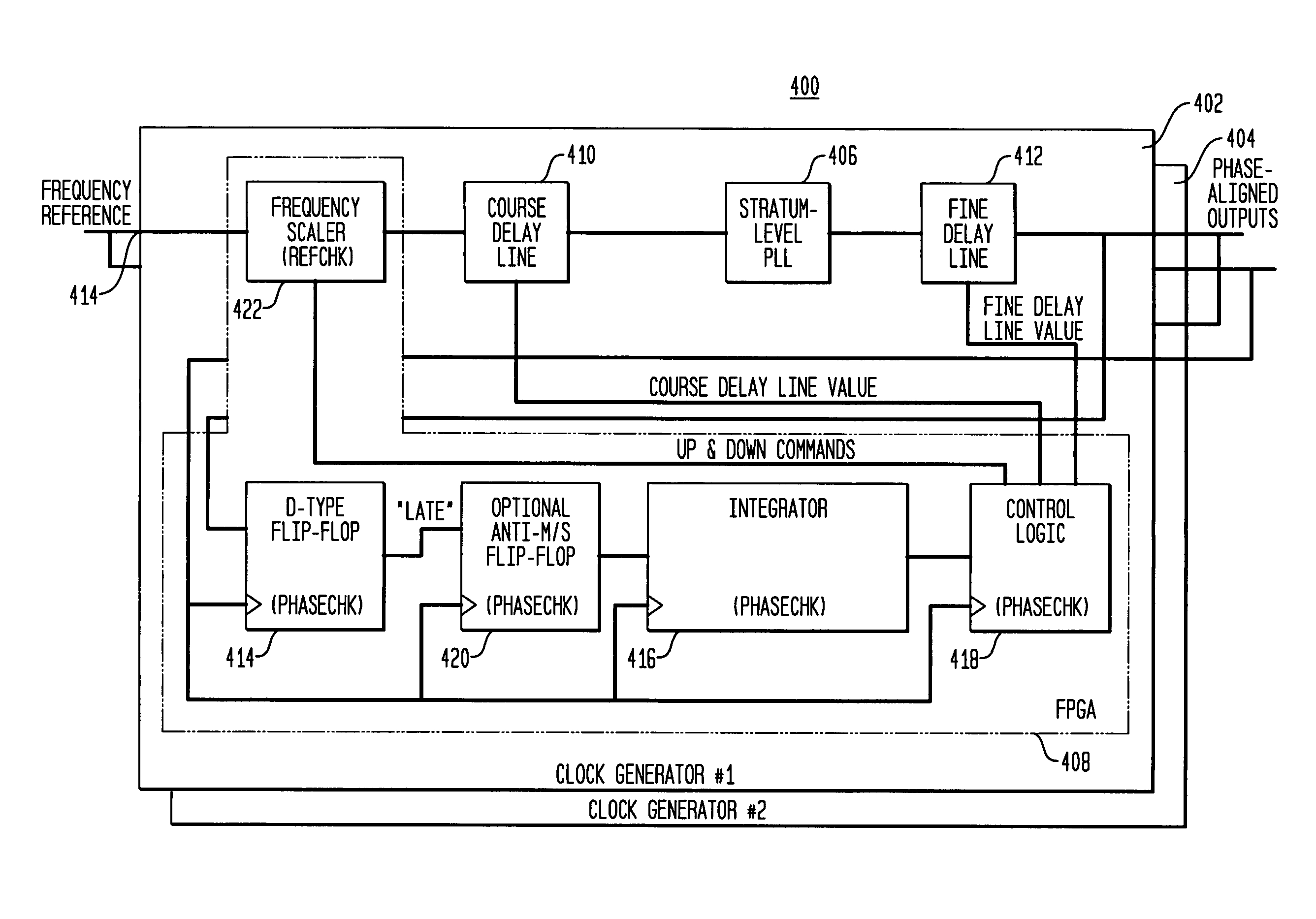
[0018] In at least one aspect, the present invention provides a phase detector and controller along with electronic delay lines that minimize or substantially eliminate the phase drift between the back-up clock from one timing module and the main clock from another timing module.

Problems solved by technology

Although the solutions provided to date have yielded frequency aligned clock signals, they have altogether overlooked the problem that the clock signals tend to drift apart in phase.
Most off-the-shelf timing modules do not provide a way to keep the output of one timing module precisely phase synchronized to the output of another.
Indeed, the phase drift may be so severe in some cases that the clock signals may deviate as much as ½ UI (unit interval or one clock period) of the output.
Until now, there has been no easily implemented solution that addresses the problem of phase drift between synchronizing clocks.

Method used


Image

  • Synchronizing unit for redundant system clocks
  • Synchronizing unit for redundant system clocks
  • Synchronizing unit for redundant system clocks

Examples


Embodiment Construction

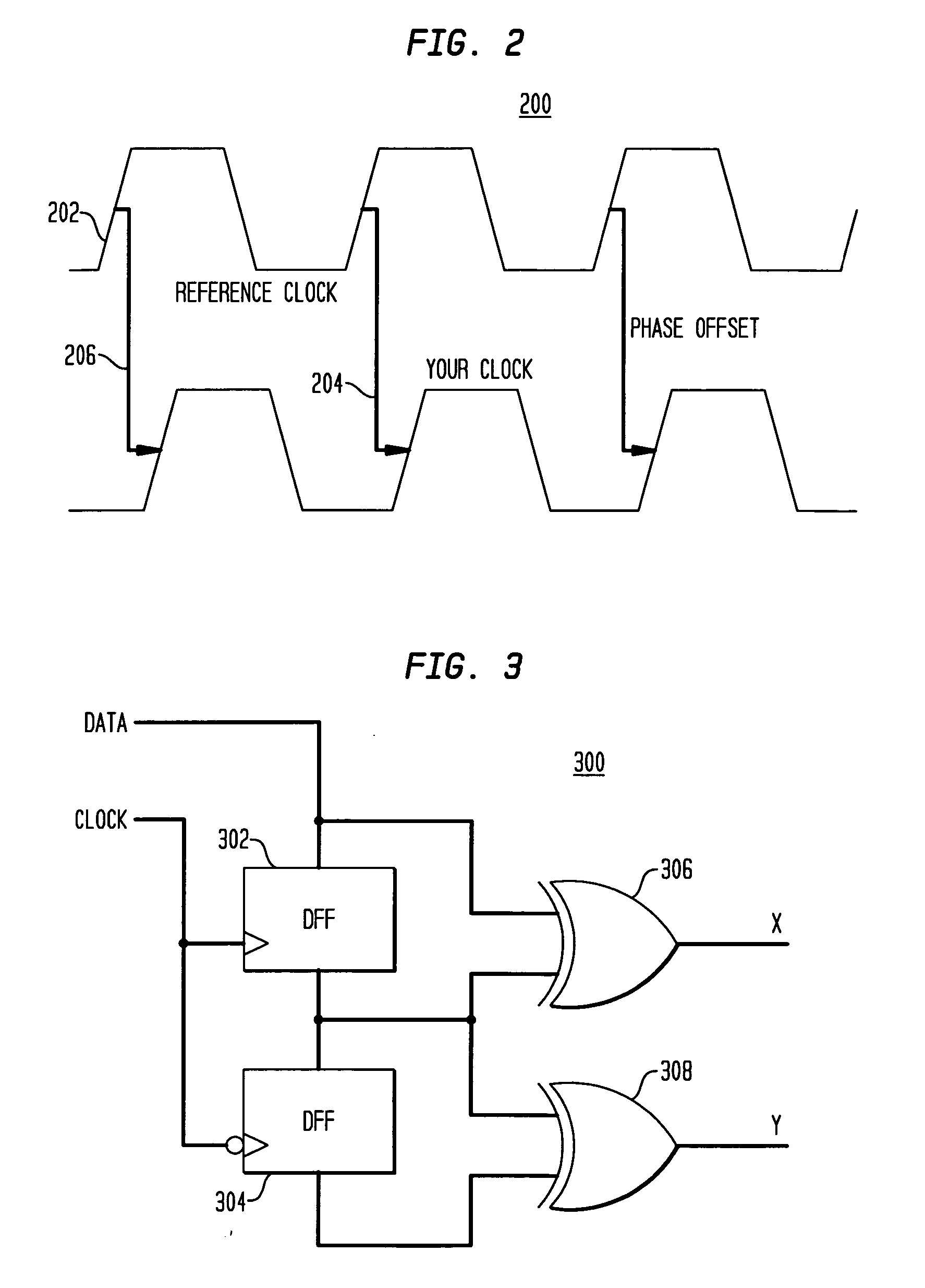
[0034] As previously discussed, the desired goal is to phase-align one clock to another even though these clocks may be frequency-matched to the same reference. The situation will be better understood from the timing diagram of

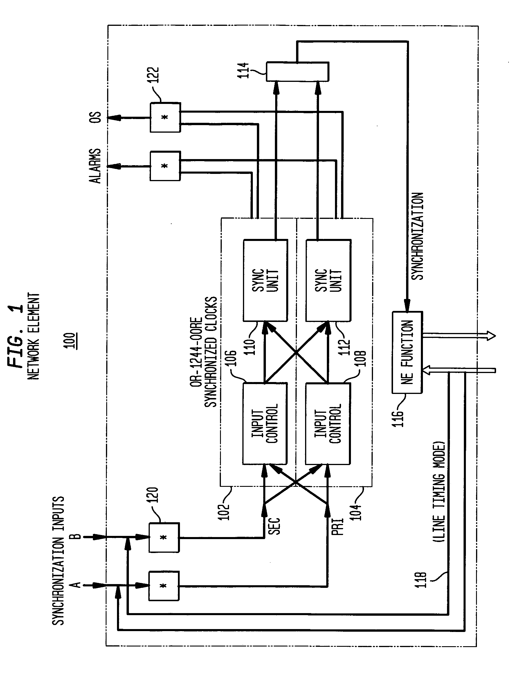
[0035]FIG. 2 which illustrates that a clock 202 may be in frequency alignment with a reference clock 204 but there is a phase difference 206 (which amounts to a timing delay) between these clocks 202 and 204. In resolving this problem it would be advantageous to utilize the existing phase-locked-loop generating the clocks. This would also suit the existing architecture specified by the GR-1244-CORE criteria.

[0036] A standard phase detector, such as the HOGGE phase detector illustrated in FIG. 3, is one type of phase detector that has been applied to correct the clock phase differences. The HOGGE circuit 300 shown in FIG. 3 includes two D-type flip-flops 302, 304 coupled in an arrangement with Exclusive-OR Gates (XOR) 306 and 308.

[0037] In operation, the HOG...


PUM


Abstract

Phase detecting and alignment of an active and a back-up clock are provided by a detector and controller. Two delay lines of differing resolution function to delay the clock and are themselves controlled to minimize or substantially eliminate the phase drift between the back-up clock from one timing module and the main clock from another timing module. In particular, both a coarse delay line and a fine delay line are adjusted based on set thresholds that are used to determine the direction of the necessary phase correction for each of the delay lines. In one particular embodiment, the coarse delay line governs the gross phase adjustments which propagate through the timing module and are, in turn, utilized to make finer adjustments to the fine delay line and achieve minimal phase delay between the main clock and the backup clock.

Description

[0001] This application claims priority from Ser. No. 601487,499, filed Jul. 15, 2003, the entire contents of which are incorporated by reference herein in its entirety.BACKGROUND [0002] 1. Field of the Present Invention [0003] The present invention relates to synchronizing clocks and, more particularly, to synchronizing clocks in order to minimize and substantially eliminate the phase drift that arises between the clocks. [0004] The present invention is applicable to any process or device for the synchronization of clocks. However, since the invention has a particular market applicability, it is appropriate to discuss the invention in terms of an industry-accepted clock synchronization schema. One such schema is known as the GR-1244-CORE criteria. [0005] 2. Related Art [0006] The GR-1244-CORE criteria, formulated by Telcordia (formerly Bellcore), sets forth a recommended schema for “Clocks for the Synchronized Network: Common Generic”. This schema is the authority on system design ...

Claims


Application Information

Patent Timeline
Patent Type & Authority Applications(United States)
IPC IPC(8): H03L7/00H04J3/06H04L7/00
CPCH03L7/00H04L7/0037H04L7/0083H04J3/0688
Inventor GALIBOIS, JOSEPH F.
Owner SIEMENS COMMUNICATIONS INC
Learn More