Resistive temperature device (RTD) module with improved noise immunity

a technology of resistive temperature device and noise immunity, which is applied in the direction of instruments, heat measurement, line-transmission details, etc., can solve the problems of significant disadvantage, increased refresh rate, and inability to measure signals correctly, so as to improve noise immunity, improve noise immunity, and reduce the delay in sampling

Active Publication Date: 2005-03-10
SCHWEITZER ENGINEERING LABORATORIES
View PDF10 Cites 29 Cited by
  • Summary
  • Abstract
  • Description
  • Claims
  • Application Information

AI Technical Summary

Benefits of technology

[0008] Accordingly, the present invention, in one aspect is a system for improving noise immunity for a resistive temperature device (RTD) module, comprising: an RTD system which includes a plurality of resistive temperature devices (RTDs) and an RTD bank assembly to which the RTDs are connected, the RTD bank assembly including a current source applied successively to the RTDs connected thereto, a switching means for switching the current source successively between the plurality of RTDs in a known sequence, and a measurement assembly for measuring the voltage drop across each RTD when the current source is connected thereto, the RTD system further including a calculation circuit for calculating the resistance of the RTD from the current applied thereto and the voltage drop thereacross; a plurality of low pass filters associated, respectively, with the plurality of RTDs, wherein when the voltage across an RTD is applied to its associated low pass filter, the low pass filter charges over time, wherein the voltage on the low pass filter is not used in calculating resistance of an RTD until the low pass filter associated with the RTD reaches a preselected level of charge wherein the plurality low pass filters are charged in turn and the voltage thereon sampled; and a system for successively precharging low pass filters associated, respectively, with successive RTDs prior to sampling thereof, so that delay in sampling is significantly reduced.
[0009] In another aspect, the present inv...

Problems solved by technology

If the induced AC signal exceeds the operating range of the RTD module, the measured signal will be incorrect.
Such an increase in refresh rate is unacceptable in many cases, since it allows too much t...

Method used


Image

  • Resistive temperature device (RTD) module with improved noise immunity
  • Resistive temperature device (RTD) module with improved noise immunity
  • Resistive temperature device (RTD) module with improved noise immunity

Examples


Embodiment Construction

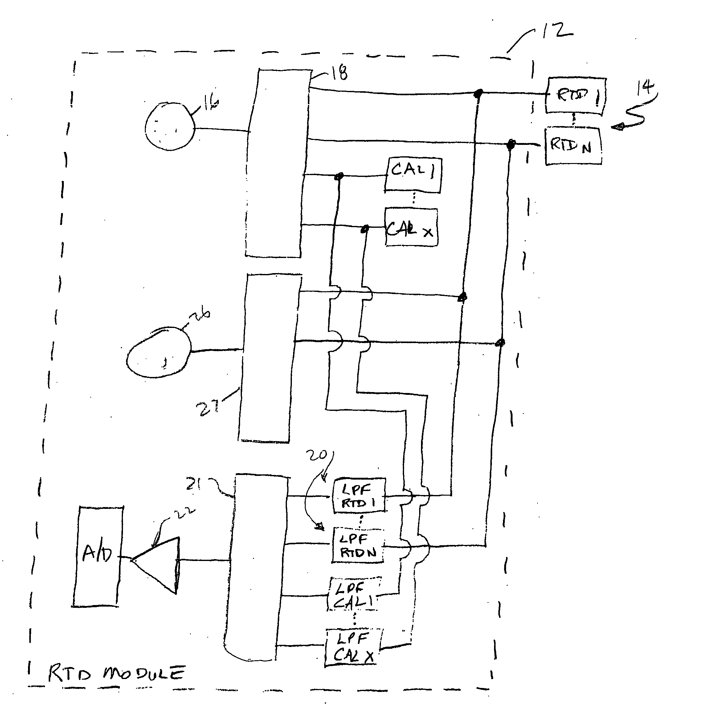
[0013]FIG. 1 shows a block diagram of the system of the present invention for improving noise immunity for a resistive temperature device (RTD) module without at the same time significantly increasing the system refresh rate, i.e. the time to carry out one sampling sequence of the RTDs associated with the module. As indicated above, an RTD is a device which changes resistance in a known manner in response to a change of temperature in the environment in which the RTD is located. Typical operating environments for an RTD include motors, generators and similar devices. The change in resistance in the RTD is determined by an RTD module which applies a current to the RTD from a highly accurate current source. The voltage drop across the RTD as a result is then determined and the resistance of the RTD at that point in time is then calculated.

[0014] Typically, an RTD module will serve a plurality of RTDs; a current signal will be applied to each RTD in turn. An RTD module may include a s...


PUM


Abstract

An RTD system includes multiple pluralities of RTDs and RTD bank assembly to which each plurality of RTDs are connected. Each RTD bank assembly includes a current source for the RTDs connected thereto, a multiplexer switching system for switching the current source successively between the RTDs, and a measurement function for measuring the voltage drop across the RTDs produced by the current source. The system includes a circuit for determining resistance of the RTD from the current applied thereto and the voltage drop there across. The system further includes a plurality of low pass filters associated, respectively, with each RTD, wherein the low pass filters are charged before the voltage measurement is made. The system includes a precharging arrangement where the low pass filter associated with the next RTD in a voltage sampling sequence is precharged, so that the delay between sampling of the voltage from the low pass filters associated with successive RTDs is significantly reduced. The system further includes low pass filters associated with calibration resistors which permit sampling of voltage values from the RTDs prior to the low pass filters associated therewith being fully charged, without error which would otherwise occur.

Description

TECHNICAL FIELD [0001] This invention relates generally to resistive temperature device (RTD) modules, and more specifically concerns a system for reducing / eliminating AC noise from the RTD voltage signal when the RTD is connected in an AC voltage environment, such as in a motor. BACKGROUND OF THE INVENTION [0002] A resistive temperature device (RTD) in operation responds to a change of temperature in its immediate vicinity (such as the windings of a motor) with a change in its resistance. The relationship between the change of resistance relative to a change in environmental temperature for each type of RTD is known. A current is applied to the RTD and the voltage drop across the RTD in response is determined. The resistance of the RTD is then calculated. The calculated resistance is then typically compared to a look-up table relating resistance to temperature to determine the environmental temperature. The RTD depends upon an accurate current source to provide accurate temperature...

Claims


Application Information

Patent Timeline
IPC IPC(8): G01K7/16G01K7/20G01K7/21G01K15/00H04B3/02H04B3/28
CPCG01K1/026G01K7/20H04B3/28H04B3/02G01K15/00
Inventor MATTOON, CARL V.MOONEY, TRAVIS L.
Owner SCHWEITZER ENGINEERING LABORATORIES
Why Eureka
Try Eureka