Circular polarization antenna and composite antenna including this antenna

a composite antenna and antenna technology, applied in the direction of polarised antenna unit combinations, resonant antenna combinations, independent non-interacting antenna combinations, etc., can solve the problems of affecting the design of the vehicle, reducing the thickness of the antenna, and affecting the performance of the vehicle, so as to reduce the space for mounting antennas for a plurality of types of waves and improve the mountability and attachability of the antenna to the vehicle. , the effect of simple power feed structur

Inactive Publication Date: 2005-03-10
FUJITSU GENERAL LTD
View PDF5 Cites 71 Cited by
  • Summary
  • Abstract
  • Description
  • Claims
  • Application Information

AI Technical Summary

Benefits of technology

[0018] According to the present invention, a circular polarization antenna having a simple power feed structure and able to receive a circular polarized wave is provided. Further, various types of antennas can be provided on a thin type dielectric body and can be provided on a dielectric body of the vehicle, so the design of the vehicle is not liable to be impaired and the antenna is not liable to be damaged or stolen. Further, by making the thin type dielectric body a transparent film, the field of vision of the driver is not liable to be blocked. Still further, by assembling other antennas which must be mounted in the vehicle into this thin type antenna as much as possible, the space for mounting antennas for a plurality of types of waves is reduced and cable

Problems solved by technology

However, in the patch antenna disclosed in Japanese Unexamined Patent Publication (Kokai) No. 2002-135045 etc., since a substrate was used, the thickness of the antenna was liable to end up becoming larger, reduction of thickness difficult, and the design of the vehicle impaired.
Further, when not providing this patch antenna on the roof of the vehicle, but on the front windshield etc., since a patch antenna must be provided with a substrate and planar ground conductor having at least a certain area, there also

Method used


Image

  • Circular polarization antenna and composite antenna including this antenna
  • Circular polarization antenna and composite antenna including this antenna
  • Circular polarization antenna and composite antenna including this antenna

Examples


first embodiment

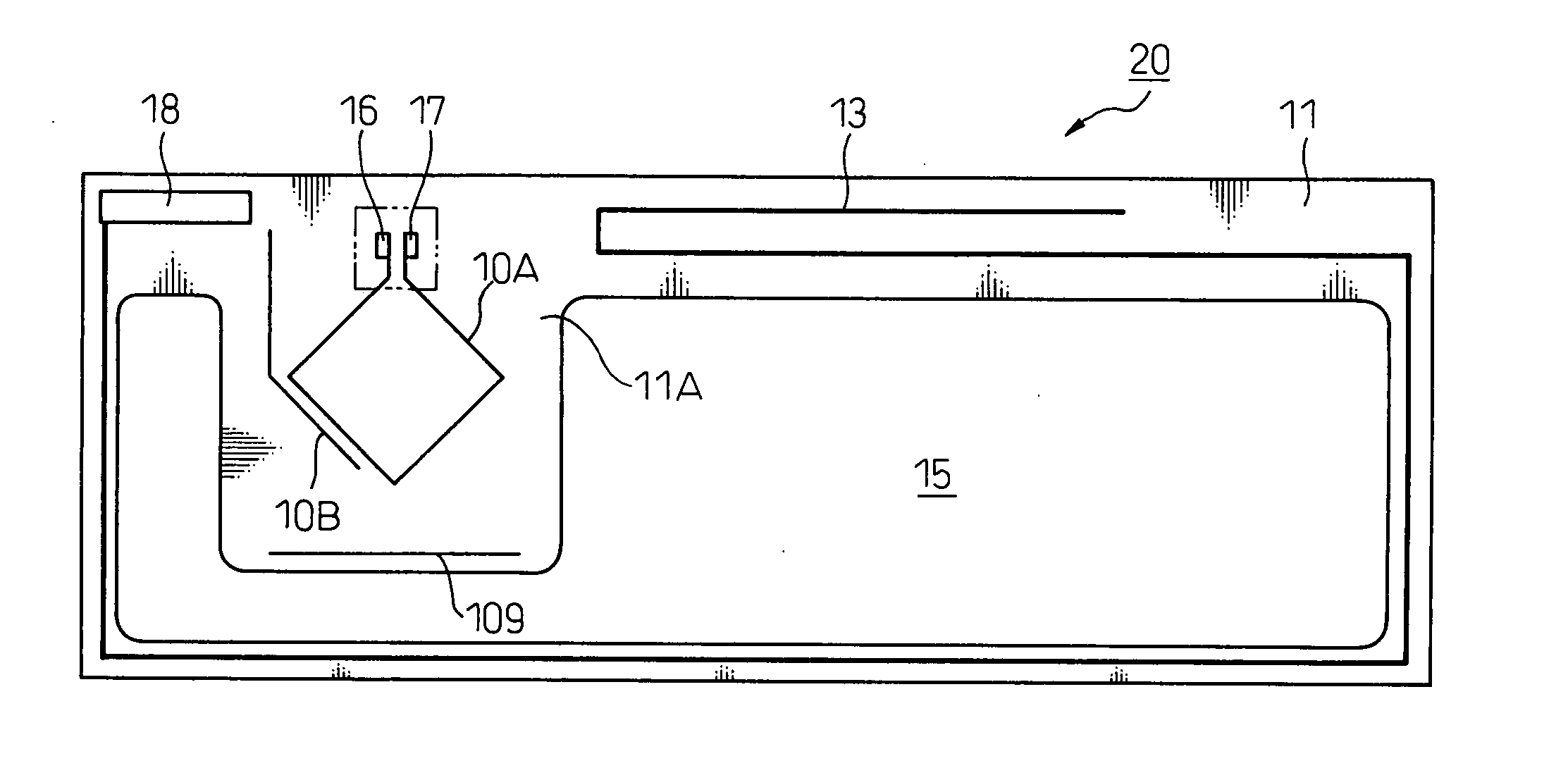
[0131] Further, in this mark 1, the mark 1 is formed a broken line or a dotted line 2. This is because if the mark 1 is formed by a continuous straight line, this continuous straight line will function as an antenna, so will exert influence upon the reception performance of the circular polarization antenna 10.

second embodiment

[0132]FIG. 4A shows an embodiment of the mark in which the outer shape of the mark 1 formed by the broken line or dotted line is made the same as the outer dimensions of the connector 21. In the second embodiment, if peeling off the peeling sheets of the two-sided adhesive tape, then, as shown in FIG. 4B, adhering the connector 21 onto the transparent film 11 so that the mark 1 is hidden by the connector 21, the connection terminals 22 and 23 of the connector 21 can be correctly connected to the power feed terminals 16 and 17 on the transparent film 11.

[0133]FIG. 5A shows a second embodiment in which the mark 1 is formed by brackets 3. The brackets 3 may be formed at positions indicating four corner portions of the connector 21 so as to be hidden by the connector 21 or at positions of an outer shape slightly larger than the outer shape of the connector 21. The shape of the mark 1 is not limited to these brackets 3.

[0134]FIG. 5B shows a third embodiment in which the mark 1 is formed...


PUM


Abstract

When configuring a film antenna for receiving a circular polarized wave, at least one loop antenna is formed on a transparent plastic film and, at the same time, a non-powered element constituted by a wire-shaped conductor independent from the antenna conductor configuring the loop is arranged near this loop antenna. The non-powered element arranged on the side of the loop antenna is configured by a first part and a second part. The first part is made close to the loop antenna in a substantially parallel state. When a monopole antenna is used in place of the loop antenna, by combining this with a wire-shaped conductor orthogonal to this, it becomes possible to receive a circular polarized wave by a configuration providing a power transfer part between the two. It is also possible to configure a composite antenna by mounting another antenna on the transparent plastic film. This antenna can be used as an antenna of a navigation system.

Description

CROSS-REFERENCE TO RELATED APPLICATION [0001] This application claims priority from, and incorporates by reference the entire disclosure of, Japanese Patent Applications [0002] (1) No. 2003-209615, filed on Aug. 29, 2003. [0003] (2) Nos. 2004-043178 and 2004-043239 filed on Feb. 19, 2004. [0004] (3) No. 2004-185084, field on Jun. 23, 2004.BACKGROUND OF THE INVENTION [0005] 1. Field of the Invention [0006] The present invention relates to a circular polarization antenna, a composite antenna having a plurality of antennas including this antenna combined therein, and a receiver, a navigation system, etc. using this antenna, more particularly relates to a circular polarization antenna used for a film antenna used adhered to a transparent windshield etc. of a mobile body such as an automobile, an antenna formed in a transparent windshield of a mobile body such as an automobile, a composite antenna including this antenna, and a navigation system using this antenna. [0007] 2. Description o...

Claims


Application Information

Patent Timeline
IPC IPC(8): H01Q1/32H01Q1/12H01Q7/00H01Q9/30H01Q21/24H01Q21/28
CPCH01Q1/1271H01Q7/00H01Q21/28H01Q21/24H01Q9/30
Inventor OGINO, KAZUSHIGEUMEZAWA, YOSHIOTAKAYAMA, KAZUONAGAO, KOJITSURUTA, KATSUHIRO
Owner FUJITSU GENERAL LTD
Why Eureka
Try Eureka