Microfluidic system

a microfluidic system and microfluidic technology, applied in the field of microfluidic systems, can solve the problems of gas bubbles in the syringes that tend to get stuck in the bore rather than rising to the top, and the fluid flow rate is unknown, so as to achieve a simple and low pressure rating

Active Publication Date: 2005-03-10
BLACKTRACE HLDG
View PDF28 Cites 24 Cited by
  • Summary
  • Abstract
  • Description
  • Claims
  • Application Information

AI Technical Summary

Benefits of technology

[0016] Preferably, the microchannel has an outlet which is pressurised to the same degree as the, or each, reservoir so that the whole system operates at equal pressure. This ensures that, in a system that employs passive valves (also known as check valves) in the pumps, there will be no flow through the system as a result of pressure differentials between the inlet and outlet. The system is also generally simpler to implement than a differentially pressurised system.
[0017] Alternatively, the outlet may be pressurised to a different extent than the, or each, reservoir. If it is at a higher pressure, then passive valves could also be used without the risk of forward flow through the system. This has the additional benefit that variations in pressure in the input reservoirs would not result in flow variations through the system. However, preferably the outlet is pressurised to a lesser extent than the, or each, reservoir and may even be left open to atmosphere. This has the advantage that the pump can have a lower pressure rating as it only has to push against the frictional pressure drop across the microchannel. This arrangement will require the use of active valves to stop the pressure difference causing additional flow through the system as a result of the pressure differential. A throttle may be provided on the outlet side of the microchannel to ensure that the pressure within the microchannel does not drop to the extent that the fluids will start to degas and boil.

Problems solved by technology

The result is that gas bubbles in the syringe tend to get stuck in the bore rather than rising to the top.
Bubbles can also get trapped in the valves.
The effect of this is that fluid flow rate is unknown and unpredictable transients can occur in the flow.
This would solve the problem, but results in an increase in the dead volume of the pump which is undesirable, and also increases the minimum flow rate possible.
We have used this approach and it works well, but it is complicated and prohibitively expensive to use commercially.

Method used


Image

  • Microfluidic system
  • Microfluidic system
  • Microfluidic system

Examples


Embodiment Construction

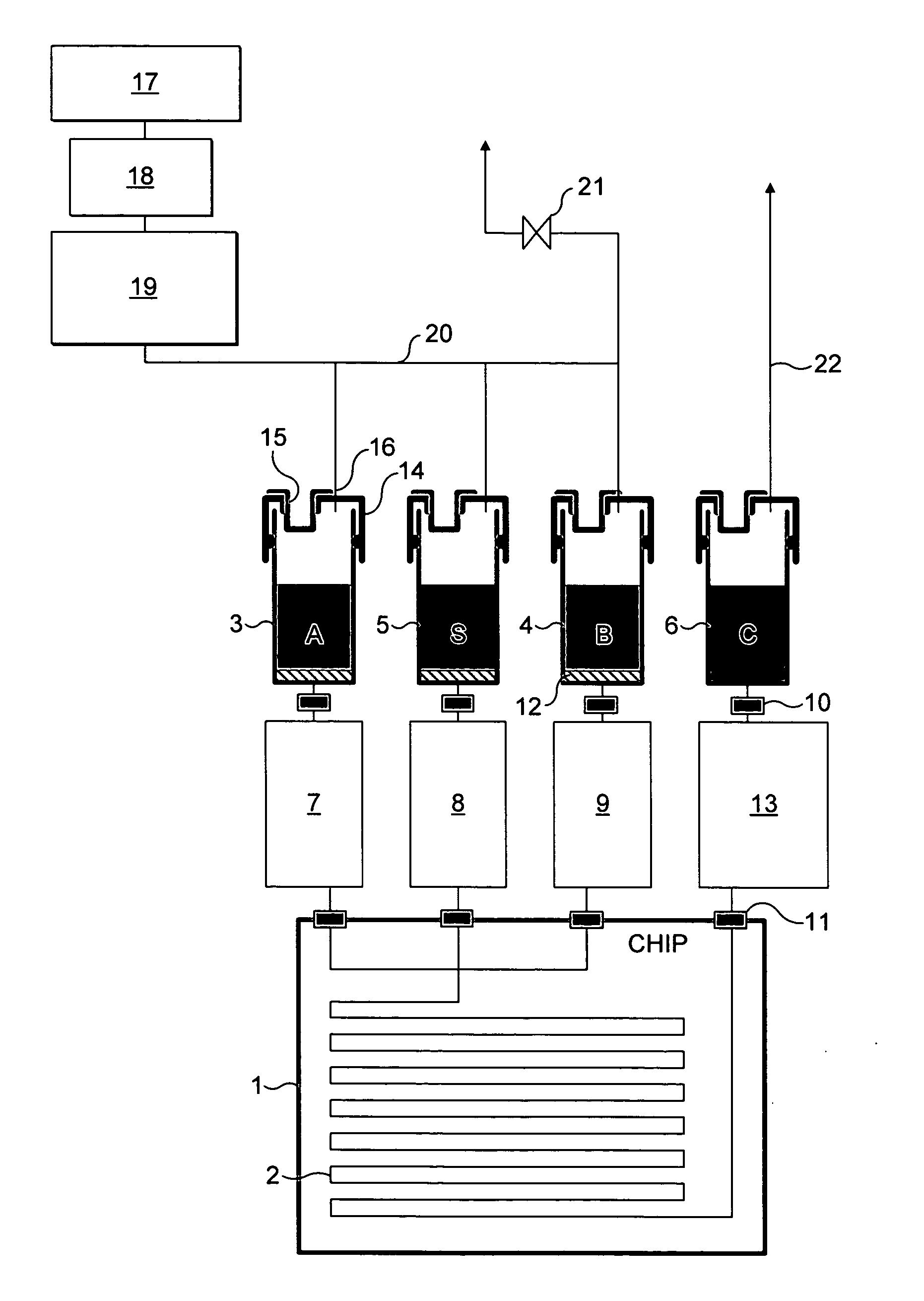
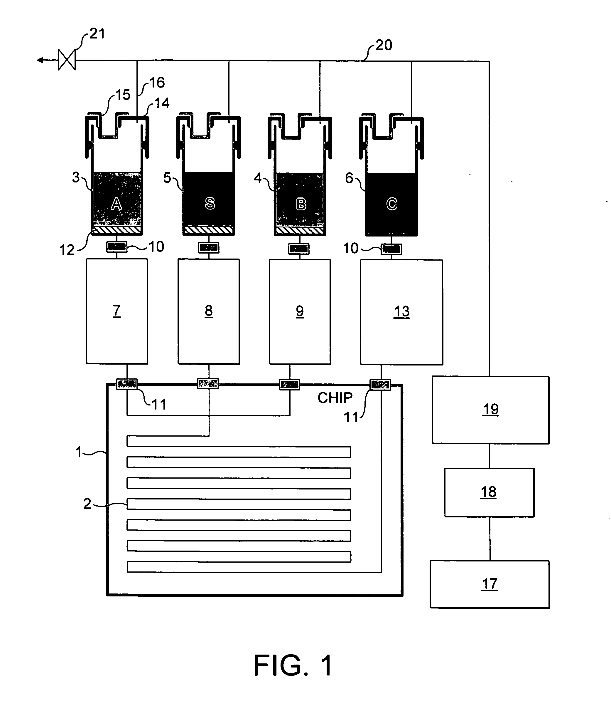
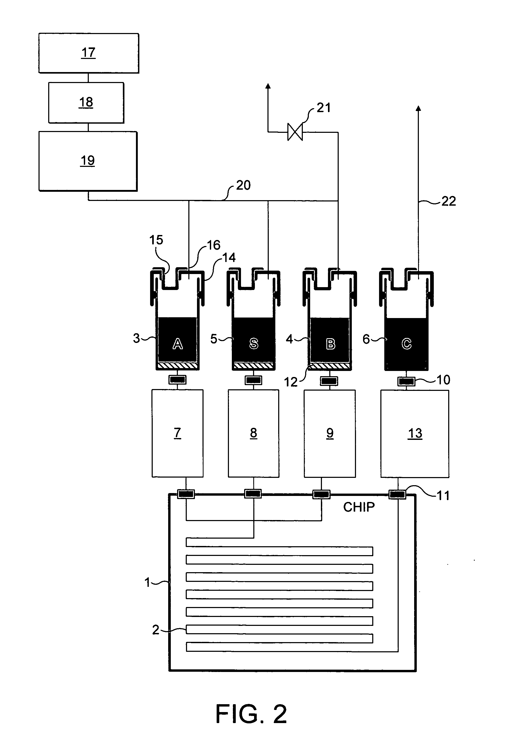
[0035] The examples shown are microreactors. Although, the invention is equally applicable to other microfluidic systems such as Micro Total Analysis Systems (μTAS), or lab on a chip devices.

[0036] The terms “microfluidic system”, “microreactor” and “microchannel” are believed to be terms which are clearly understood in the art. The terms are best understood functionally as relating to systems / reactors / channels which are sufficiently small that diffusional mixing predominates and efficient heat transfer occurs, resulting in optimal reaction conditions in the microchannel. The dimensions should be sufficiently small that the flow results in a low Reynold's number (3) and a predominantly laminar flow regime.

[0037] Generally at its narrowest point, the reactor / channel should have, in cross-section, a maximum internal dimension of 5-500 μm, and preferably 5-250 μm. However, it is possible to envisage a channel which has a long thin cross-section having a dimension greater than 500 μm,...


PUM

PropertyMeasurementUnit
flow rateaaaaaaaaaa
diameteraaaaaaaaaa
boiling pointaaaaaaaaaa

Abstract

A microfluidic system comprising a microchannel (2), a pressurised reservoir (3-5) of fluid and a positive displacement pump (7-9) downstream of the reservoir for pumping the fluid from the reservoir to the microchannel.

Description

CROSS REFERENCE TO RELATED APPLICATIONS [0001] The present application claims priority to Great Britain Application No. 0320337.9, filed Aug. 29, 2003, which application is incorporated herein fully by this reference. BACKGROUND OF THE INVENTION [0002] Field of the Invention [0003] The present invention relates to a microfluidic system. [0004] One of the current challenges in microfluidics is pumping at a very low flow rate, in particular in the 10 nl / min-10 μl / min range (or even as much as 1000 μl / min). A common method is Electro Osmotic Flow (EOF), also known as electrokinetic flow, used in microreactors and μTAS devices such as biological analysis chips. EOF works well if the properties of the fluid, such as Zeta potential and viscosity, are known. The main applications of such a technique are water based biological microfluidic systems where reagents are supplied with the system and have fixed and known properties. For other situations where the fluid properties are unknown EOF ...

Claims


Application Information

Patent Timeline
Patent Type & Authority Applications(United States)
IPC IPC(8): B01L3/00F04B19/00G01N1/00
CPCB01L3/50273B01L2200/0684G01N35/1095B01L2400/0487F04B19/006B01L2300/14Y10S977/904
Inventor GILLIGAN, MARK PETER TIMOTHYHOMEWOOD, PHILIP JAMESBRIANT, JOHN PHILIPLOVATT, ANDREW MARK
Owner BLACKTRACE HLDG
Why Eureka
Try Eureka