Variable capacitance element

Inactive Publication Date: 2005-03-10
MURATA MFG CO LTD
View PDF11 Cites 19 Cited by
  • Summary
  • Abstract
  • Description
  • Claims
  • Application Information

AI Technical Summary

Benefits of technology

To overcome the problems described above, preferred embodiments of the present invention provide a variable capacitance element which prevents the displacement of a movable elect

Problems solved by technology

However, when a variable capacitance element is used, an external force such as vibration and impact may be applied to the substrate.
This is a disadvantage.
In this case, returning the variable

Method used


Image

  • Variable capacitance element
  • Variable capacitance element
  • Variable capacitance element

Examples


Embodiment Construction

Preferred embodiments of the present invention will be described below with reference to drawings.

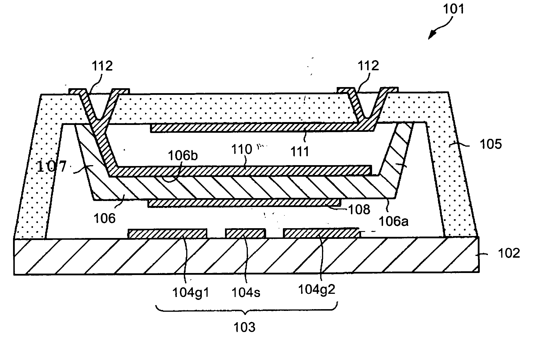
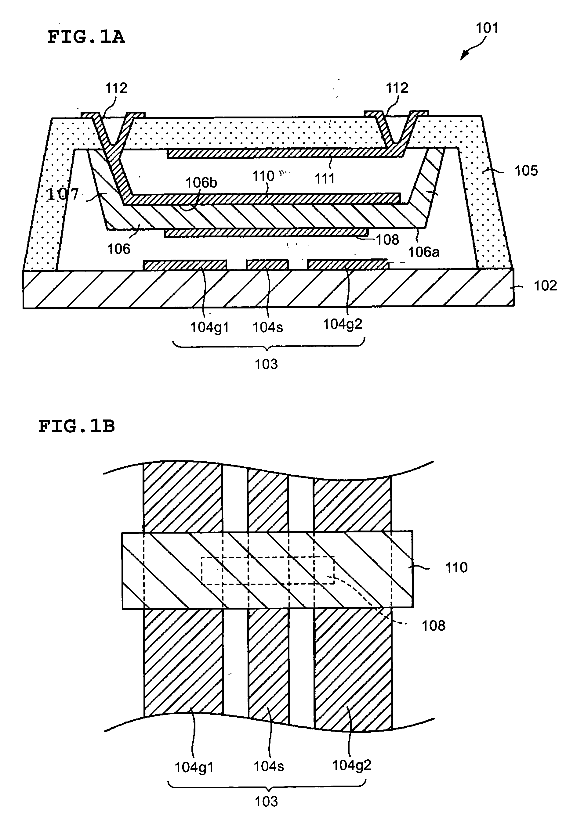
FIG. 1A shows a schematic section diagram of a first preferred embodiment of a shunt switch element, which is a variable capacitance element.

A shunt switch element 101 according to the first preferred embodiment includes a substrate 102 including a dielectric. A coplanar line 103 is provided on the substrate 102. The coplanar line 103 defines a high frequency signal conducting portion for conducting high frequency signals of about 5 GHz or more, for example, as described above. Three lines 104g1, 104s and 104g2 are aligned on the substrate 102 at a desired interval. The middle line 104s is a signal line. The lines 104g1 and 104g2 on both sides of the signal line 104s are ground lines. An upper member 105 including glass, for example, is provided on the substrate 102 over the coplanar line 103 by leaving a certain amount of space in between. The upper member 105 and the substrate 102...


PUM


Abstract

A variable capacitance element includes a coplanar line or signal conduction and a movable body, which are vertically displaced through a supporting bar and which are provided on a substrate. A movable electrode is provided between a first driving electrode and second and third driving electrodes which are movable electrodes. Voltage is applied between the movable electrodes, such that one of the movable electrodes is pressed against the coplanar line through a dielectric film. Thus, high frequency signals conducting through the coplanar line are shut off. When voltage is applied between the other electrodes, the movable electrode and the dielectric film are moved apart from the coplanar line. Thus, high frequency signals are conducted through the coplanar line.

Description

BACKGROUND OF THE INVENTION 1. Field of the Invention The present invention relates to a variable capacitance element included in a high-frequency circuit. In particular, the present invention relates to a variable capacitance element, for use as, for example, a variable capacitance switch or a variable capacitor. In this case, the variable capacitance switch performs switching operations on high-frequency signals by changing electrostatic capacitance. 2. Description of the Related Art Generally, a variable capacitor is known. A variable capacitor displaces, for example, a movable electrode with respect to a fixed electrode by using electrostatic gravity so as to change the spacing between these electrodes. Thus, the electrostatic capacitance is variably selected. This kind of conventional variable capacitor is substantially similar to an electrostatically-driven switch as disclosed in Japanese Unexamined Patent Application Publication No. 2000-188050. The variable capacitor in...

Claims


Application Information

Patent Timeline
IPC IPC(8): H01H59/00H01P1/12
CPCH01H59/0009H01H2059/0072H01G5/40H01G5/16H01P1/127
Inventor FUJII, YASUTAKAKOBAYASHI, SHINJIKAWAI, HIROSHITAKEMURA, KOJIKONAKA, YOSHIHIROKOBAYASHI, MASATO
Owner MURATA MFG CO LTD
Why Eureka
Try Eureka