
Structure of LED decoration lighting set

a technology of led decoration and lighting set, which is applied in the direction of lighting and heating apparatus, application, color-music apparatus, etc., can solve the problems of affecting the aesthetic delicateness, restricting the application of led, and unsatisfactory viewing angle, etc., and achieves efficient structure, wide viewing angle, and uniform brightness

Inactive Publication Date: 2005-03-10
AMAZING INT ENTERPRISE
View PDF2 Cites 78 Cited by
  • Summary
  • Abstract
  • Description
  • Claims
  • Application Information

AI Technical Summary

Benefits of technology

[0005] An object of this invention is to provide a lighting set which can address the prior art deficiencies by providing a wide viewing angle, uniform brightness and an efficient structure.
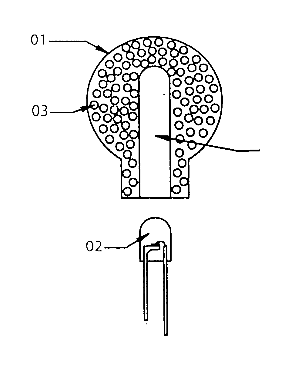
[0008] The bubbles densely found in the decorative part enable it to become a combination of a spherical concave and convex lens. When the light emitted from the illuminant transmits in the decorative part, a large amount of non-sequential diversion, conversion, refraction and reflection take place and this entirely changes the original transmission path of the light beam. When the light exits from the surface of the decorative part, diffusion of light takes place, i.e. when the light is emitted from the illuminant, efficient diffusion, refraction, conversion is in progress, maximizing the entire lighting effect of the decorative part. Light diffusion agent, glass powder and fluorescein can be added to improve light emission.
[0010] 1. Material is saved. The product is lighter. As there are plenty of bubbles in the decorative part, the volume taken up by the bubbles and the groove for the illuminant can help save up to 10% or more of the materials used. The weight decreases.
[0012] 3. The light is highly diffusive and color mixing is possible. When the light transmits in the decorative part, the original transmission path is entirely modified by the densely structured bubbles. This solves the problem of a narrow viewing angle.

Problems solved by technology

The set-back of the LED as a light source, namely, the narrow viewing angle and the uneven diffusion of light beam on the surface of the decoration lighting set, not only affects the aesthetic delicateness, but also restricts the application of an LED.
Although the viewing angle of this “wide viewing angle LED” prior art is widened through the lighting decoration, the viewing angle is not satisfactory.
Moreover, the distance between the LED and all the surfaces of second device has to be fixed at an identical length, and the shape of the second device is limited to a spherical shape.
As a result, the light beam projected on the surface is uneven.
This largely restricts the shape of the device as it is difficult to overcome the problem brought by the dispersion effect of the light beam.
Moreover, as a light diffusion agent is used, this undermines the transmission of the light beam.

Method used


Image

  • Structure of LED decoration lighting set
  • Structure of LED decoration lighting set
  • Structure of LED decoration lighting set

Examples


first embodiment

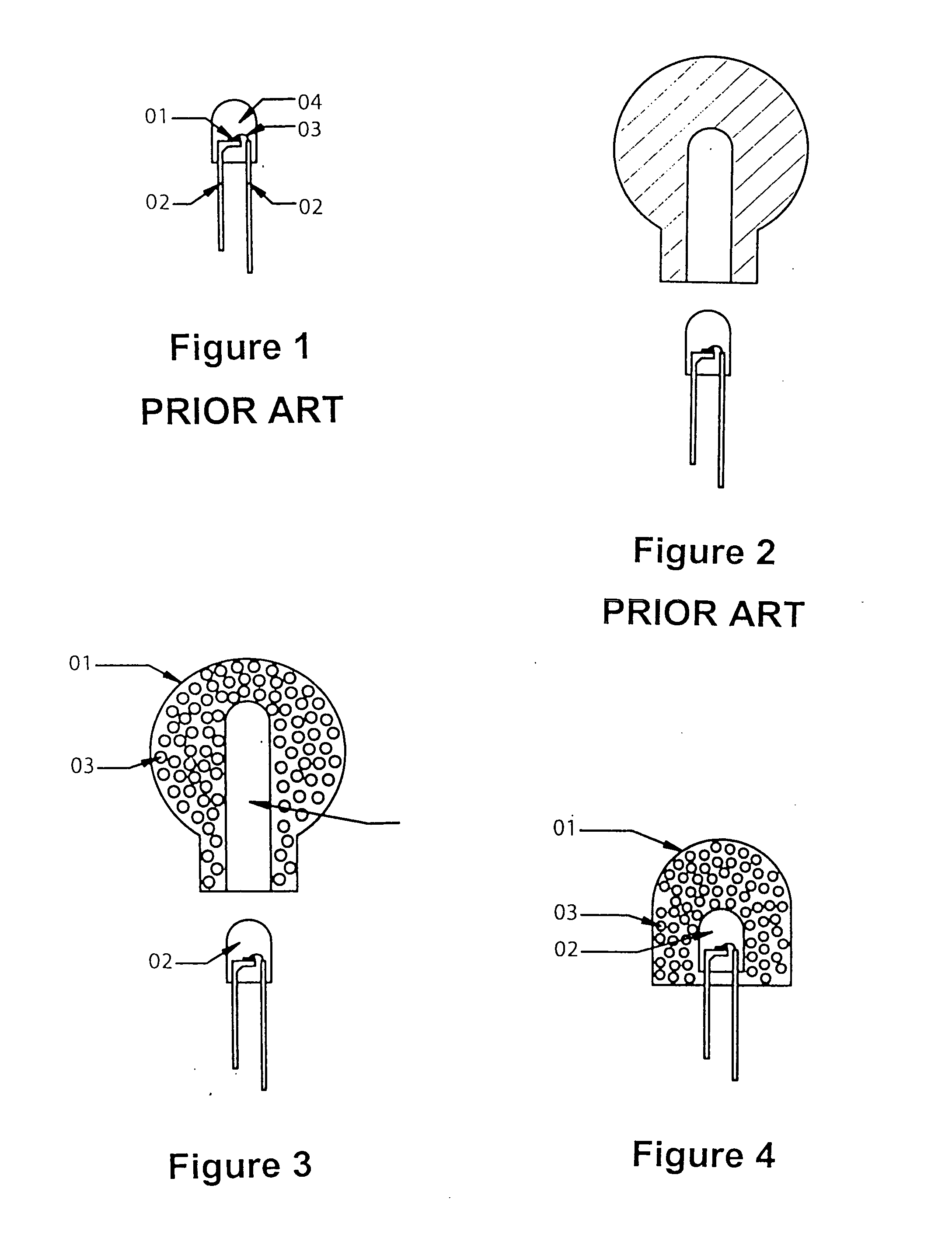
[0030] In FIG. 4, the illuminant 2 is a LED. The encapsulated LED 2 is cast into the decorative part 1 with bubbles. Two of them bond together to form one entire part. The material used for the decorative part 1 is transparent resin. There are at least three layers of bubbles 3 along the transmission path of the light beam in the decorative part 1. The total volume of bubbles 3 takes up 30% or more of the total volume of the decorative part 1. The volume of bubbles 3 can be varied immensely, i.e. several times. The decorative part is cast as a hemisphere. Cylindrical, tower, oval and various shapes can be applied. this invention described here is to provide a lighting set with a wide lighting angle.

second embodiment

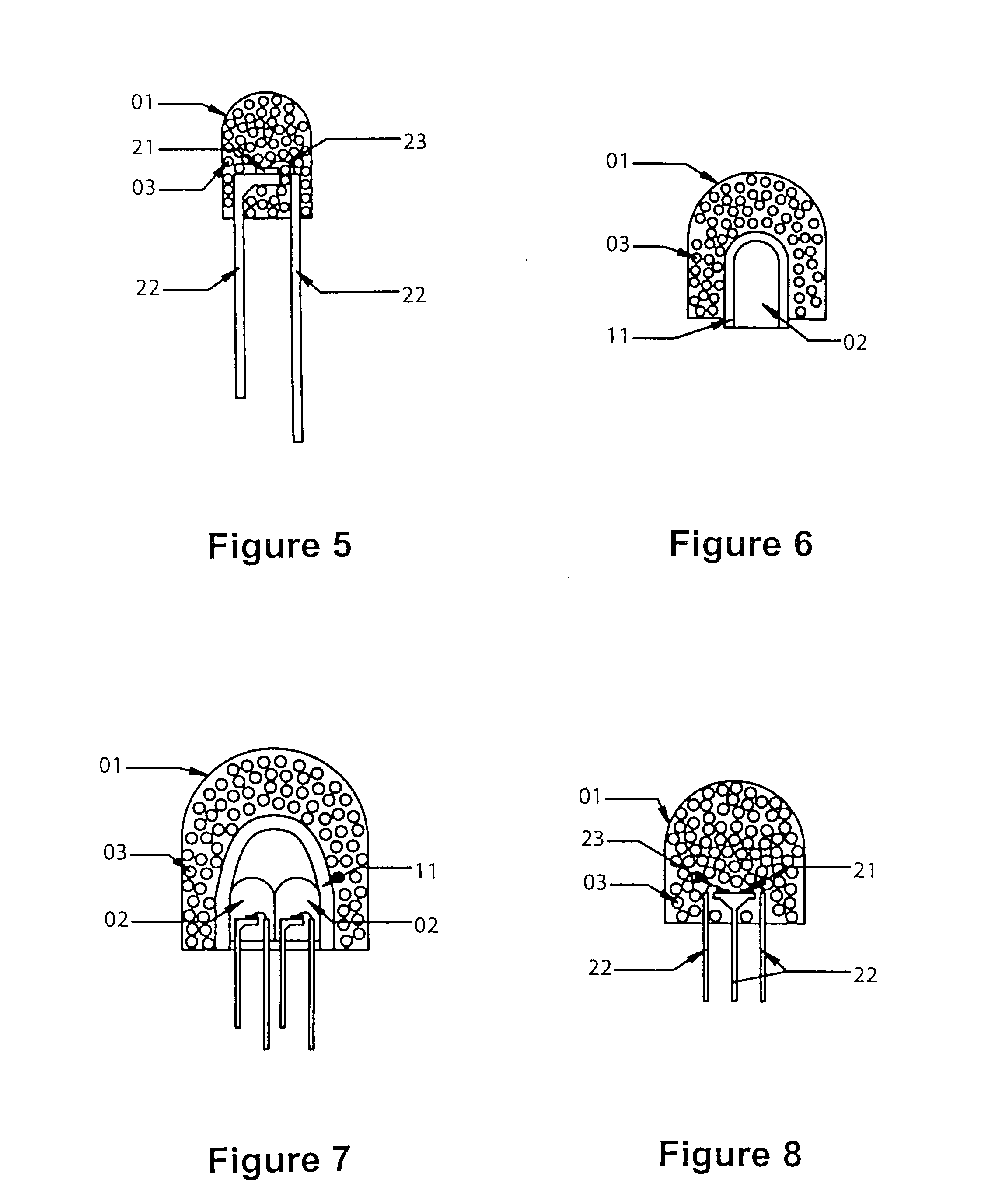
[0031] In FIG. 5, the transparent resin of a traditional LED is replaced by the decorative part 1 with bubbles 3 inside. The highly transparent material used for the decorative part 1 is transparent resin. The decorative part 1 with bubbles 3 inside is cast as the outer shell of the common LED. LED die 21, terminal pins 22 and wire 23 can be made together with the decorative part 1 as one whole set. The decorative part 1 shown in the figure is hemispherical. It can be cylindrical, rectangular, tower, oval and triangular. this invention described here is to provide a LED of common size with high diffusive luminous intensity.

third embodiment

[0032] In FIG. 6, the decorative part 1 with bubbles 3 inside is made as a pocket. this invention described here is hemispherical. It can be rounded, rectangular, tower, oval, triangular and in various shapes. In the pocket of the decorative part 1, there is a groove 11 for the illuminant 2 to be inserted into. The shape of the groove 11 matches the contour of the illuminant 2 so that the illuminant 2 can be inserted in flexibly. One LED 2 can be inserted in the decorative part 1. As shown in FIG. 6, more than one LED 2 can be inserted.

[0033] As shown in FIG. 7, the fourth embodiment of this invention, LEDs 2 with different colors can be inserted in the decorative part 1 to create a different combination of colors. The size of groove 11 depends on the size of the combination of the LED 2, so that the light emitted from LED 2 can be directly and uniformly transmitted to the combination of bubbles in the decorative part 1 maximizing the luminous intensity. This fourth embodiment of th...


PUM


Abstract

This invention relates to the functional features of lighting devices, particularly, the structure of refractors of an LED decoration lighting set. It is composed of a decorative part made of transparent materials and an illuminant. The illuminant is activated by an external power supply and is incorporated into the decorative part. Bubbles are found uniformly and densely in the decorative part in a region which intersects the light emitted from the illuminant. The bubbles enable the decorative part to become a combination of a spherical concave and convex lens. When the light emitted from the light-emitting part is transmitted to the decorative part, a large amount of non-sequential diversion, conversion, refraction and reflection will take place to significantly change the original transmission path of the light beam. This solves the problem of the small viewing angle of a traditional LED decoration lighting set.

Description

TECHNICAL FIELD [0001] This invention relates to the functional features of lighting devices, particularly, the structure of refractors for an LED decoration lighting set. BACKGROUND OF THE INVENTION [0002] Nowadays, lighting adds variety to the life of people, such as a home-used dim light bulb, a flashlight for a toy, and a festive decoration lighting set. One of the important criteria for decoration lighting is that the emitted light should be spread uniformly and can be viewed from all surfaces; hence, the entire contour of the decoration lighting set can be viewed maximizing the efficiency of the lighting. [0003] At the moment, an LED, as a light source, has been widely applied in the field of a decoration lighting set. FIG. 1 shows a kind of common hemispherical LED. It is composed of an LED die 1, a terminal pin 2, a wire 3 and an epoxy (resin) 4. A casting of transparent epoxy (resin) forms the protective cap and acts as lens. Light emitted from LED die 1 converges on the he...

Claims


Application Information

Patent Timeline
IPC IPC(8): F21V3/04F21V17/06
CPCF21V3/04F21V17/06F21Y2101/02F21V3/02F21K9/135F21K9/137F21K9/56F21W2121/00F21K9/232F21K9/233F21K9/64F21Y2115/10
Inventor WU, HAN WEN
Owner AMAZING INT ENTERPRISE
Learn More