Intraoperative stereo imaging system

a stereo imaging and stereo imaging technology, applied in the field of intraoperative stereo imaging systems, can solve the problem that the two-dimensional nature of fluoroscopy may not provide sufficient information for surgical navigation

Active Publication Date: 2005-03-10
XORAN TECH
View PDF23 Cites 43 Cited by
  • Summary
  • Abstract
  • Description
  • Claims
  • Application Information

AI Technical Summary

Problems solved by technology

However, the two dimensional nature of the fluoroscopy may

Method used


Image

  • Intraoperative stereo imaging system
  • Intraoperative stereo imaging system
  • Intraoperative stereo imaging system

Examples


Embodiment Construction

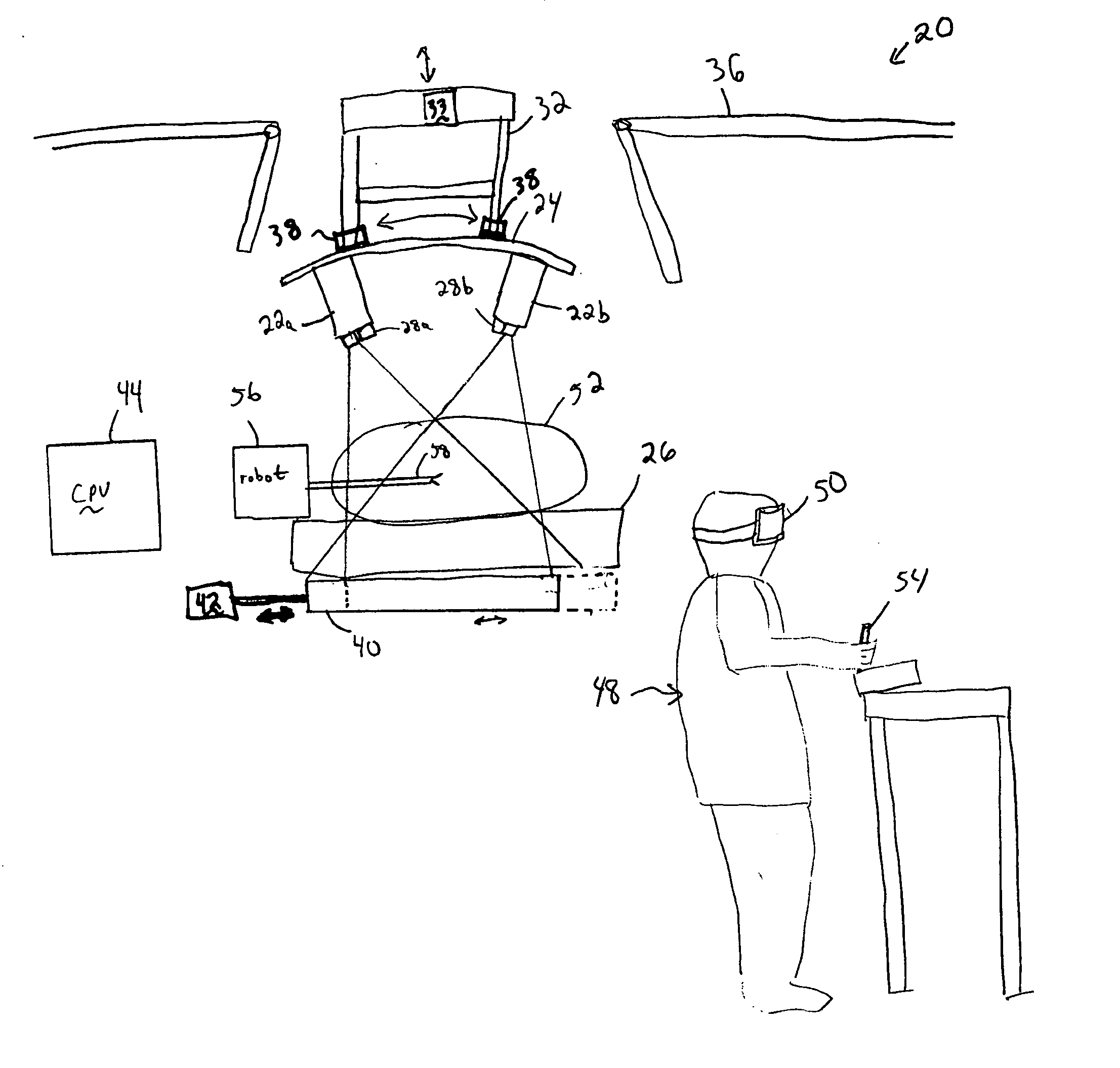
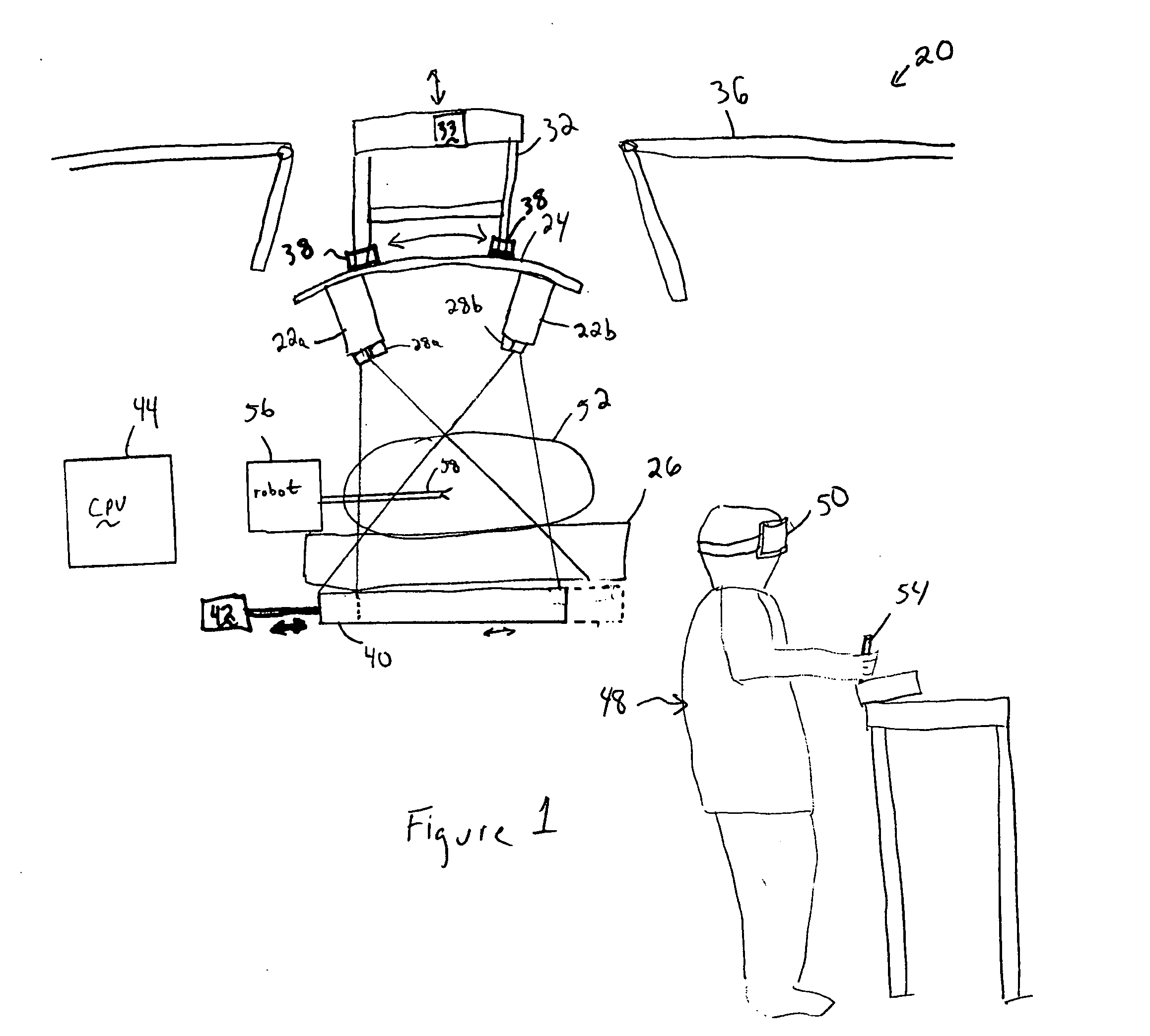
[0010] The present invention shown in FIG. 1 provides an imaging system 20 particularly useful for image-guided surgery, remotely-controlled robotic surgery or other applications where intra-operative imaging would be desired. Although potentially useful for other types of imaging systems, the present invention will be described with respect to an intra-operative CT scanning system 20.

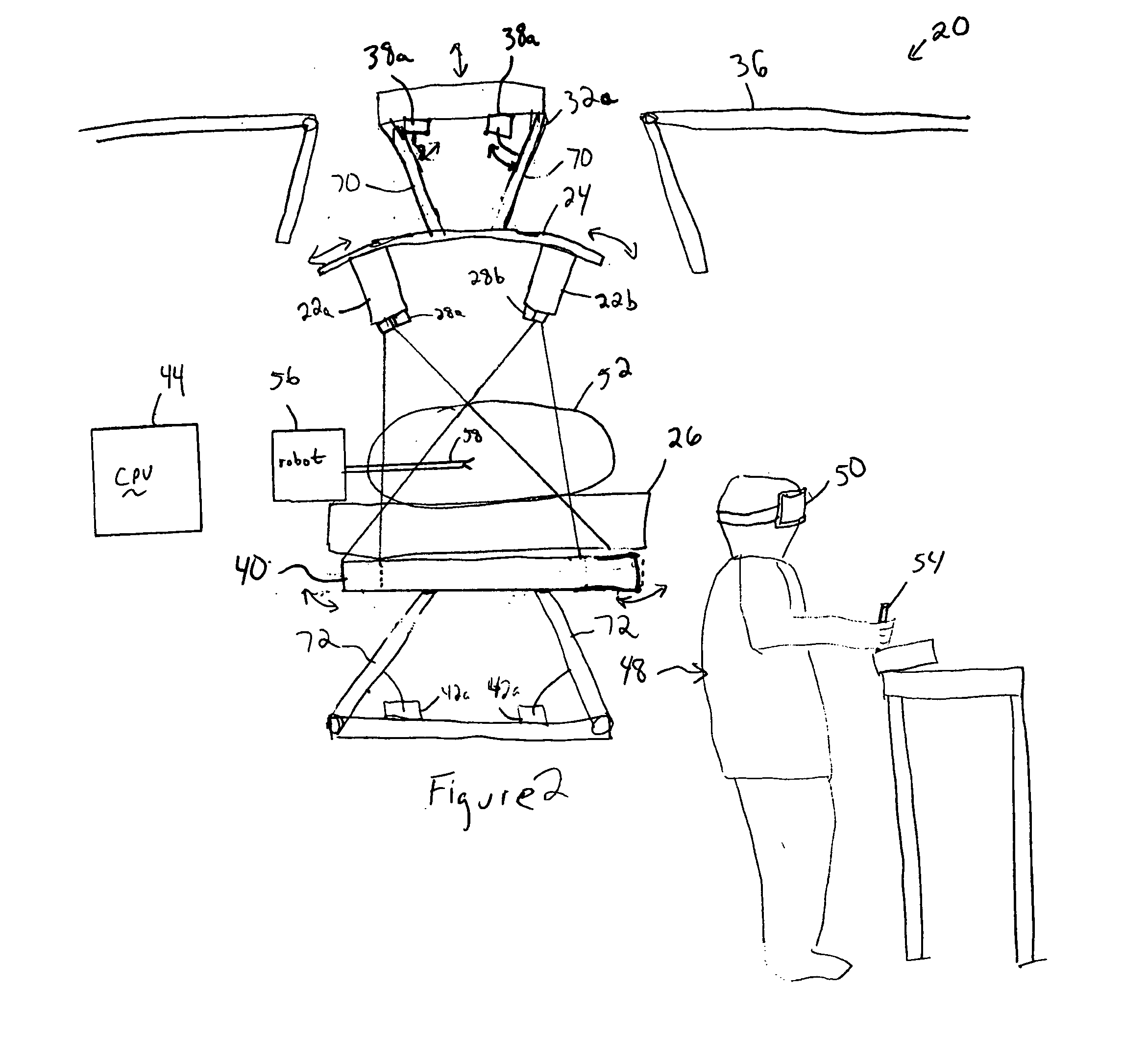
[0011] Referring to FIG. 1, the imaging system 20 includes a pair of laterally offset sources 22a, 22b both mounted on a bracket 24 above a radiolucent operating table 26. The bracket 24 is mounted to a lift 32 that is powered by a motor 33 to extend and retract down from and into the ceiling 36 above the operating table 26. The bracket 24 is coupled to the lift 32 via motorized couplings 38 for selectively moving the bracket generally along an arcuate path. Alternatively, the bracket 24 may be mounted on a robotic arm.

[0012] The sources 22a, 22b may be cone-beam x-ray sources. Each of the sources 22...


PUM


Abstract

A surgical imaging system includes spaced-apart first and second x-ray sources mounted above a patient support surface. An x-ray detector mounted below the patient support surface generates first x-ray images based upon x-rays from the first x-ray source and second x-ray images based upon x-rays from the second x-ray source. These first and second x-ray images are used to generate a stereofluoroscopic image via a stereo display for a surgeon performing image-guided surgery. The stereofluoroscopic imaging system may be used in conjunction with robotic surgery. A surgical robot operatively controls a surgical tool in an area between the first x-ray source and the x-ray detector, and between the second x-ray source and the x-ray detector. The system may optionally include a first video camera mounted proximate the first x-ray source and a second video camera mounted proximate the second x-ray source. The stereo display selectively displays the first and second video images or the first and second x-ray image, and dissolves between the sources to correlate an outer view with the fluoroscopic view.

Description

[0001] This application claims priority to U.S. Provisional Application Ser. No. 60 / 493,265 filed Aug. 7, 2003.BACKGROUND OF THE INVENTION [0002] Image guided surgery is becoming more common. Systems are utilized to take data gathered from pre-operative scans by MRI, CT scanners, ultrasounds, or the like. The data is used to generate a three-dimensional image to guide a surgeon during an operation. Often this includes some method for tracking an instrument location with respect to the image displayed by the system. Generally, the image is registered relative to locators attached to the patient. Then, the position and orientation of the surgical instruments is registered and tracked relative to the image and the patient so that the location and orientation of the instruments relative to the image is continuously displayed while the surgeon performs the surgery. However, the current image-guided surgery relies on a preoperative scan. Changes to the surgical area during surgery are not...

Claims


Application Information

Patent Timeline
IPC IPC(8): A61B6/00A61B6/02A61B19/00G03C9/00
CPCA61B6/022A61B6/504A61B19/2203G03C9/00A61B2019/5227A61B2019/5238A61B2019/5289A61B19/5212A61B2090/364A61B90/361A61B2090/376A61B34/30A61B2090/371
Inventor SUKOVIC, PREDRAGCLINTHORNE, NEALBAIR, NATHANIEL
Owner XORAN TECH
Why Eureka
Try Eureka