
Method and apparatus for inspection of reactor head components

a technology for reactor heads and components, which is applied in the direction of television systems, instruments, greenhouse gas reduction, etc., can solve the problems of not providing a robust, versatile, inspection system and/or carriage, and not developing inspection devices like those discussed above to inspect the components of the reactor head without extensive setup procedures, etc., and achieves the effect of loss of tolerances

Inactive Publication Date: 2005-03-17
R BROOKS ASSOC
View PDF42 Cites 47 Cited by
  • Summary
  • Abstract
  • Description
  • Claims
  • Application Information

AI Technical Summary

Benefits of technology

[0009] A primary object of the present invention is to provide an apparatus and method for transporting a sensor assembly to the inside a reactor head and easily, repeatedly positioning a visual inspection and / or non-destructive inspection probe into close proximity along a component of a reactor head for inspection of the component surface and / or the interior of the component, particularly, to determine the presence of flaws and predict the likelihood of the formation of flaws in the component, as well as any loss of tolerances in the component.
[0010] This object of the invention is achieved by providing a movable carriage having elevation support elements for positioning the inspection probe and providing a simple probe element which will enable 360° inspection of the exterior and / or interior of the reactor head components.
[0011] In one embodiment of the invention, the probe is constructed as an open-ended inspection collar, e.g., C- or U-shaped inspection collar, having embedded video cameras and, a non-destructive inspection device, such as an eddy-current measurement sensor, ultrasonic sensor, magnetic field sensor. In a preferred embodiment, the collar is mounted at the end of an elevator arm supported by a movable carriage and includes a magnetic inspection probe having a magnetic permeability sensor which determines the location of actual flaws in the reactor component, and also enables accurate prediction of the location of the formation of flaws at some later time.
[0012] The method of inspection of the invention involves precisely positioning the C- or U-shaped collar in close proximity to a reactor head component utilizing the video cameras, e.g. position adjacent a guide sleeve and rack assembly, such that both a 360° video inspection of the exterior surface and tolerances of the components can be performed employing the video cameras. The video cameras also enable precise positioning of an internal, non-destructive inspection device to enable a 360° non-destructive inspection of the interior of the components to be performed, e.g., an inspection of each weld of the components.

Problems solved by technology

Inspection devices, like those discussed above, have not been developed to inspect the components of the reactor head without requiring the extensive setup procedure.
None of the inspection systems of the prior art discussed above provides a robust, versatile inspection device and / or carriage for performing these inspection functions for reactor head components.
While the inspection systems of the prior art above do not solve the need for repeatedly inspecting the components of a reactor head, those systems are also quite complicated, require extensive manufacturing operations and considerable expense.

Method used


Image

  • Method and apparatus for inspection of reactor head components
  • Method and apparatus for inspection of reactor head components
  • Method and apparatus for inspection of reactor head components

Examples


Embodiment Construction

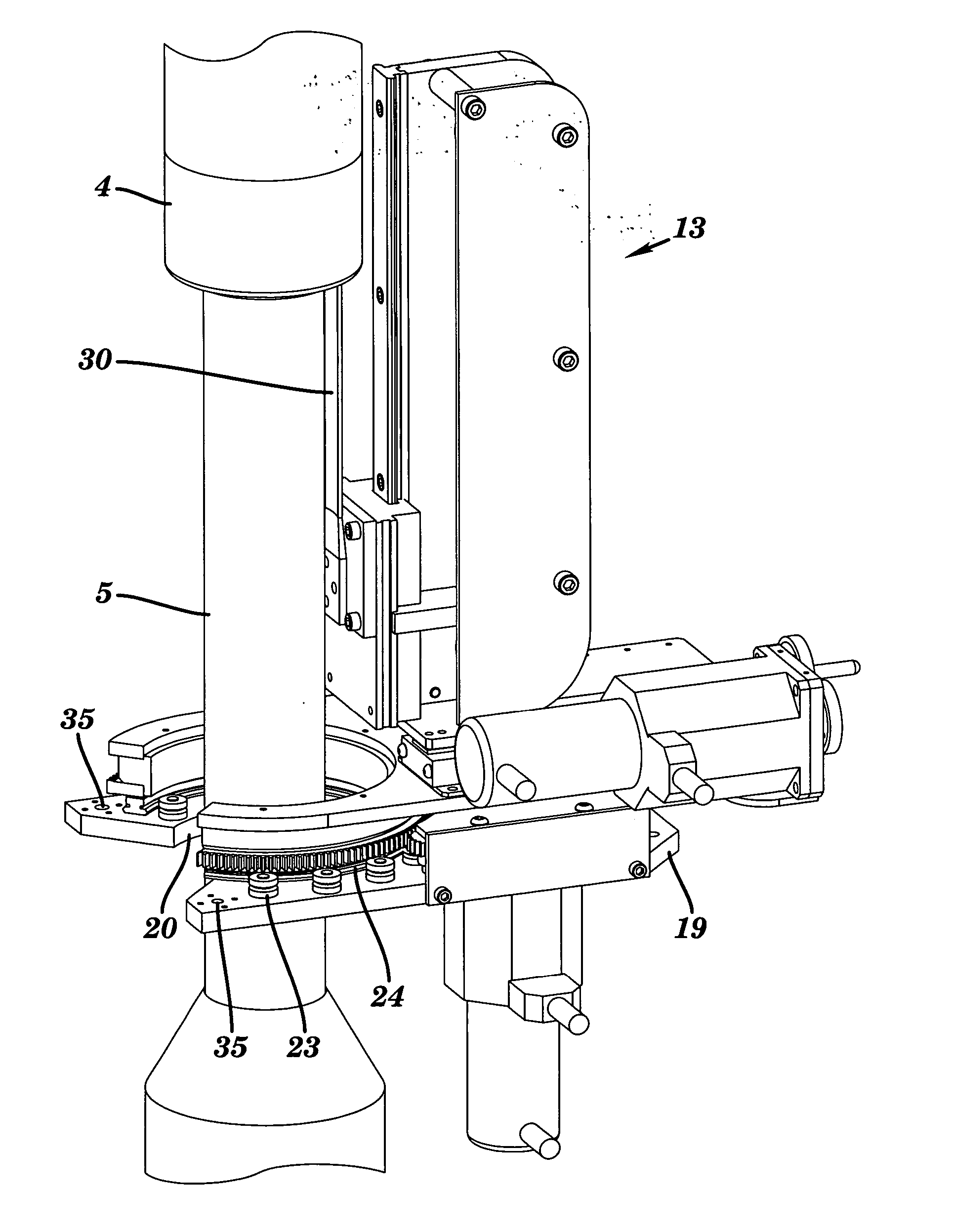
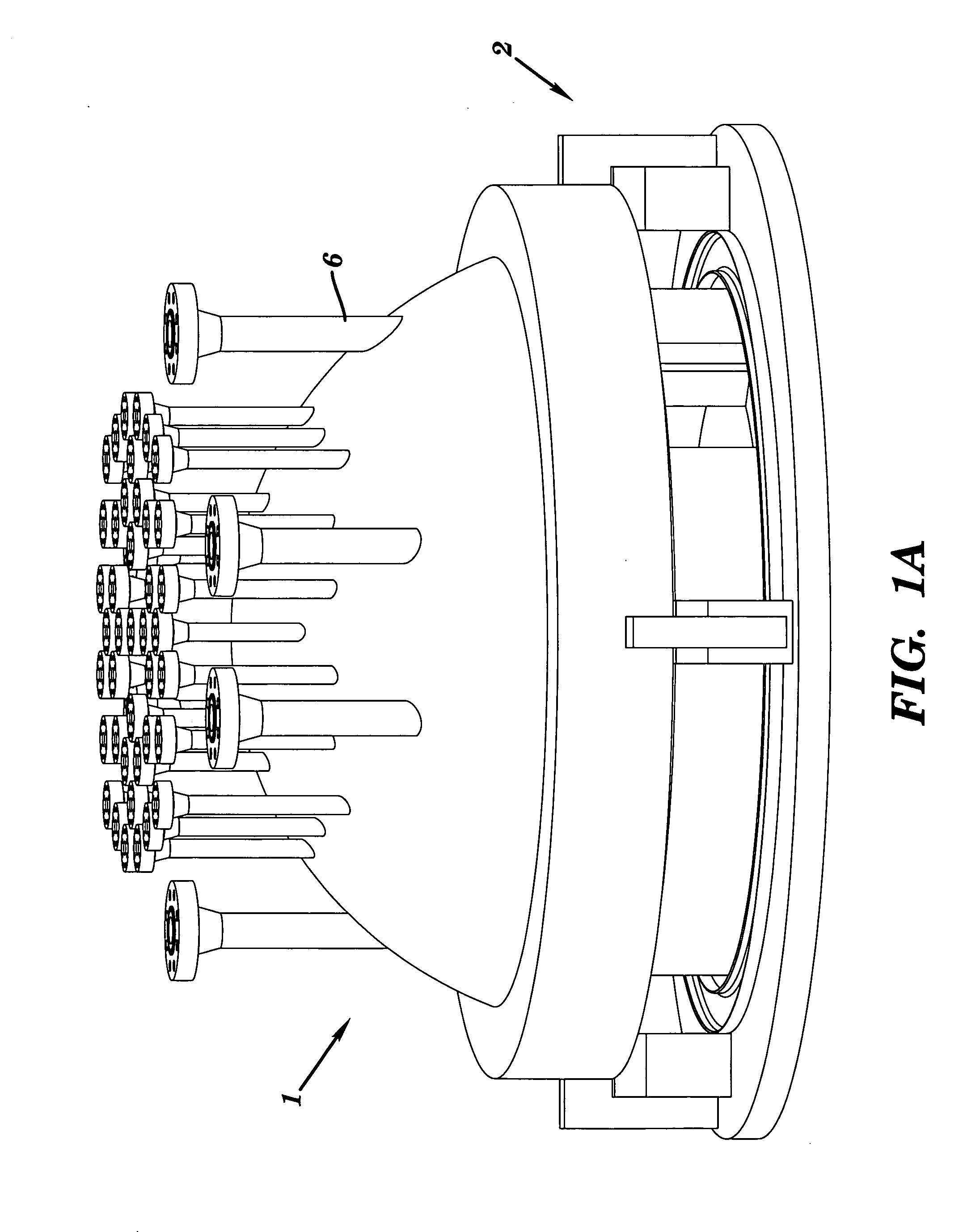
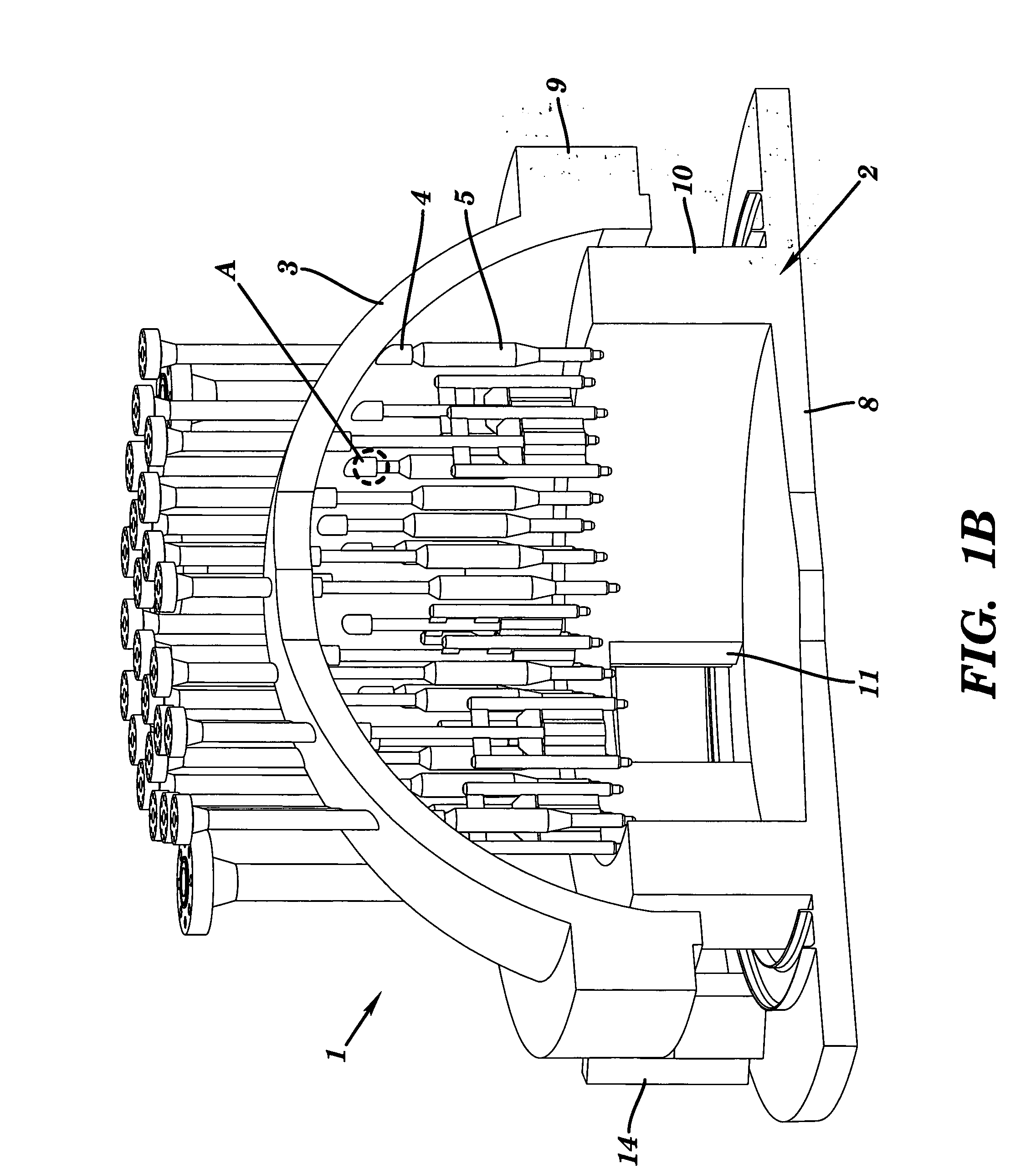
[0022] The reactor head 1 of FIG. 1A is shown to be resting on an inspection station 2; while FIG. 1B illustrates a cross sectional view of both the reactor head and the inspection station 2. Specifically, the reactor head 1 includes a shell 3 through which penetration components 4 extend and each penetration component is welded to the shell 3 by a conventional J-weld. Each penetration component 3 has a rack assembly 5 extending concentrically therein; the details of which are shown in FIG. 2. Additional in-core penetration components 6 are shown distributed around the penetration components 4 and, like the penetration components will be inspected by the inspection system of the invention. FIG. 2 illustrates in an exploded view a penetration component 4 and the rack assembly 5 concentrically assembled. Additionally, between the penetration component 4 and rack assembly 5 is positioned a thermal guide sleeve 7 which insulates the penetration component from the temperatures of the rac...


PUM


Abstract

A reactor head inspection system for use in performing a non-destructive inspection of tubular components mounted on an interior surface of a reactor head is disclosed. The inspection system includes a movable carriage assembly including a elevation arm and an inspection device mounted at a distal end of the elevation arm. The inspection device includes a C- or U-shaped collar having an interior surface of sufficient interior dimension to enable positioning of the interior surface of the collar in close proximity of an exterior surface of a tubular component and also includes a magnetic and / or eddy current sensor. A plurality of video cameras and light sources are also provided on a distal surface of the collar such that, when mounted on the elevation arm, the collar can be controllably positioned in close proximity adjacent a tubular component of the reactor head to achieve a 360° view and inspection of a surface of the tubular component.

Description

BACKGROUND OF THE INVENTION [0001] 1. Field of the Invention [0002] The invention relates to a method and apparatus for inspecting the head assembly of a reactor vessel. Particularly, the invention describes a system for performing remote external (visual) and internal (e.g. magnetic field, eddy current) inspection on site of the interior of a head of a reactor vessel during periods of servicing and recharging the reactor vessel. In particular, the method of the invention employs a sensor system which includes an ability to not only locate flaws, i.e. cracks, in the reactor head components, but also includes an ability to predict the formation of flaws by monitoring the magnetic permeability of the reactor head components. A visual inspection device of the invention functions both as a positioning device for precise location of an inspection device and as a 360° evaluation device of the surfaces of a reactor component, e.g., J-weld. Further, the internal inspection device of the inv...

Claims


Application Information

Patent Timeline
IPC IPC(8): G01N21/88G01N27/87G01N27/90G21CG21C17/003G21C17/007G21C17/01G21C17/013G21C17/017
CPCG01N29/043G21C17/017G01N2291/267Y02E30/30
Inventor DELACROIX, BRADLEY S.JEWETT, MATTHEW R.MAYFIELD, MICK D.LEWIS, RANDALL K.
Owner R BROOKS ASSOC
Learn More