
Data Communication System, Data Transmitting Apparatus, Data Transmitting Method, and Method for Determining Packet Size and Redundancy

a data communication system and data transmission technology, applied in data switching networks, two-way working systems, frequency-division multiplexes, etc., can solve problems such as increased delay, receiving terminals that cannot perform decoding, and insufficient tolerance for burst loss, so as to increase delay. , the effect of increasing the delay

Active Publication Date: 2008-06-26
SONY CORP
View PDF7 Cites 85 Cited by
  • Summary
  • Abstract
  • Description
  • Claims
  • Application Information

AI Technical Summary

Benefits of technology

[0012]In the case of packetizing data into a predetermined size and using the FEC method to perform redundant encoding on the packetized data, in order to obtain sufficient tolerance for burst loss, it is necessary to increase the number of original data packets included in an FEC encoding unit, that is, a so-called “FEC block”, or it is necessary to increase the proportion of redundant packets in the FEC block. Normally, to reduce overheads of redundant packets, the number of original data packets in the FEC block is increased. To increase the number of original data packets included in the FEC block for transmission data (encoded data) having a low data rate, it is necessary to form an FEC block by using original data packets over a plurality of time stamps, thus leading to an increase in delay.
[0017]In the data transmitting apparatus, a data size of the transmission data is acquired in each predetermined time unit, and, on the basis of the data size, a packet size of each data packet of the transmission data is determined. In this case, when the transmission data has a low data rate, by reducing the packet size, an FEC block having a sufficient number of packets can be formed on the basis of the transmission data in each predetermined time unit. The data receiving apparatus can perform decoding in the predetermined time units, whereby tolerance for burst loss can be obtained without increasing a delay.
[0020]Although there are combinations of the number k of original data packets and the number n−k of redundant packets which satisfy the expression, for example, a combination in which the total of the proportion of overheads of the original data packets and the proportion of overheads of the redundant packets is minimized is selected. In this case, the overheads can be minimized. For example, in image transmission, a high quality image can be transmitted and the amount of use of a network band can be minimized.
[0023]According to the embodiment of the present invention, in a case in which, after transmission data is packetized and the resultant data packets are redundant-encoded in predetermined time units, the encoded packets are transmitted from a data transmitting apparatus to a data receiving apparatus, a packet size is determined on the basis of a data size of the transmission data in each predetermined time unit. Therefore, sufficient tolerance for burst loss can be obtained even at a low data rate without increasing a delay.

Problems solved by technology

To increase the number of original data packets included in the FEC block for transmission data (encoded data) having a low data rate, it is necessary to form an FEC block by using original data packets over a plurality of time stamps, thus leading to an increase in delay.
In this case, even if a packet in a preceding frame in the FEC block has a loss, a receiving terminal is unable to perform decoding until all the packets in the FEC block have arrived.
This causes an increase in delay.

Method used


Image

  • Data Communication System, Data Transmitting Apparatus, Data Transmitting Method, and Method for Determining Packet Size and Redundancy
  • Data Communication System, Data Transmitting Apparatus, Data Transmitting Method, and Method for Determining Packet Size and Redundancy
  • Data Communication System, Data Transmitting Apparatus, Data Transmitting Method, and Method for Determining Packet Size and Redundancy

Examples


Embodiment Construction

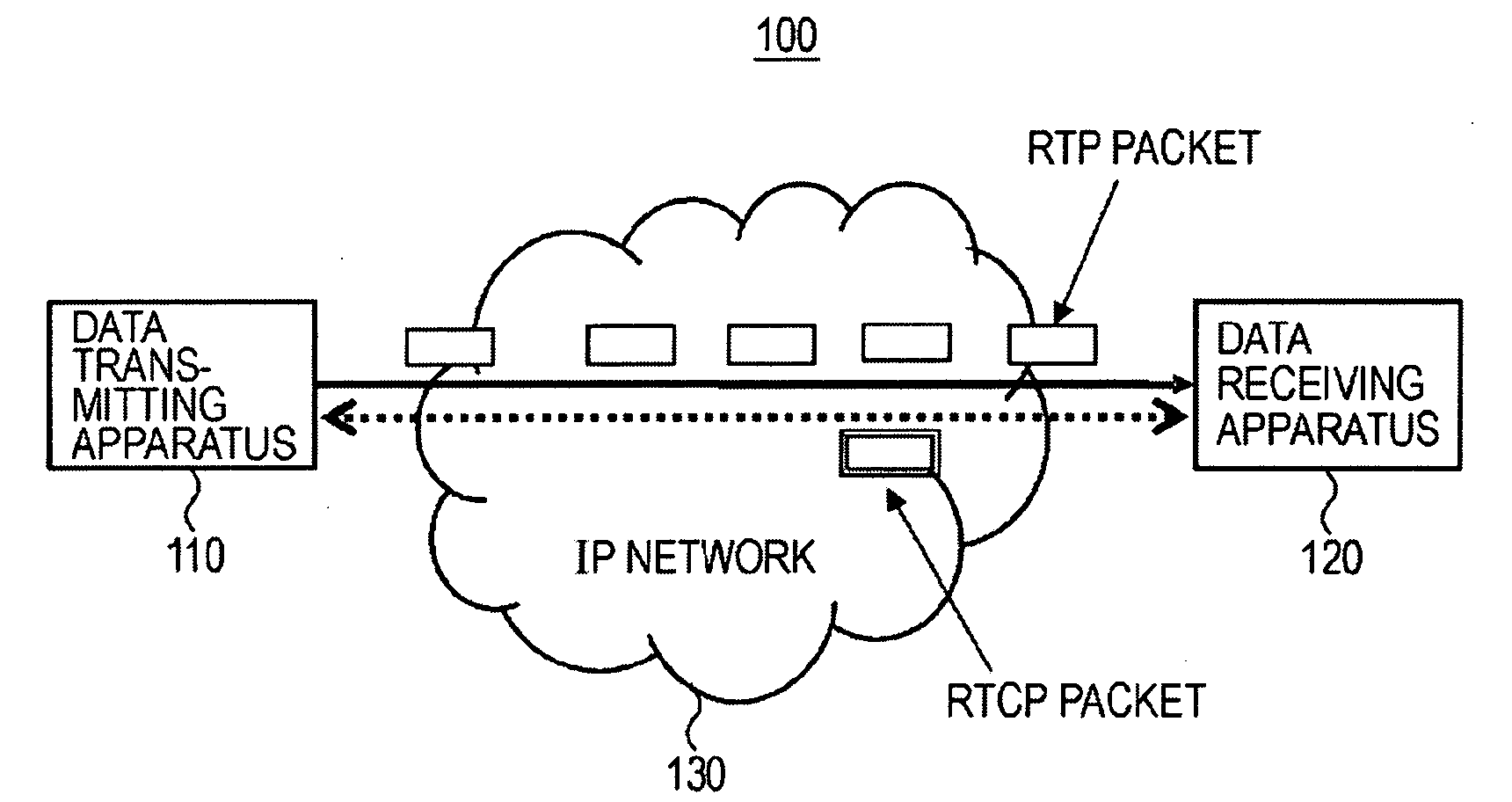
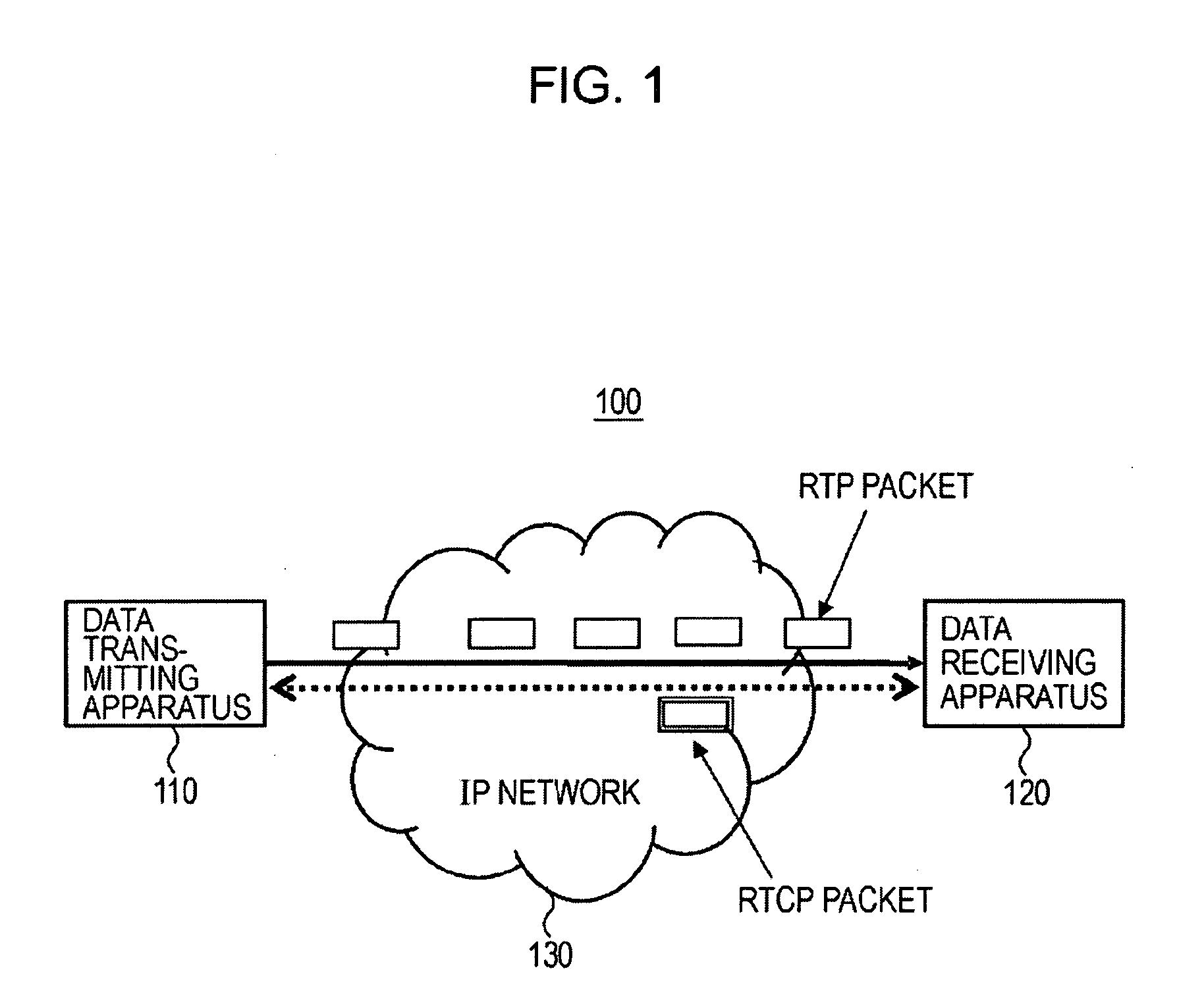
[0037]An embodiment of the present invention is described below with reference to the accompanying drawings. FIG. 1 shows an example of the configuration of a data communication system 100 according to the embodiment of the present invention. The data communication system 100 includes a data transmitting apparatus 110 and a data receiving apparatus 120. The data transmitting apparatus 110 and the data receiving apparatus 120 are connected by a network (IP network) 130.

[0038]The data transmitting apparatus 110 packetizes transmission data such as video data or audio data, performs FEC encoding, as redundant encoding, on the packetized data in predetermined time units, and transmits the resultant data to the data receiving apparatus 120. When a received FEC block includes an original data packet including a loss, the data receiving apparatus 120 restores the original data packet by performing FEC decoding.

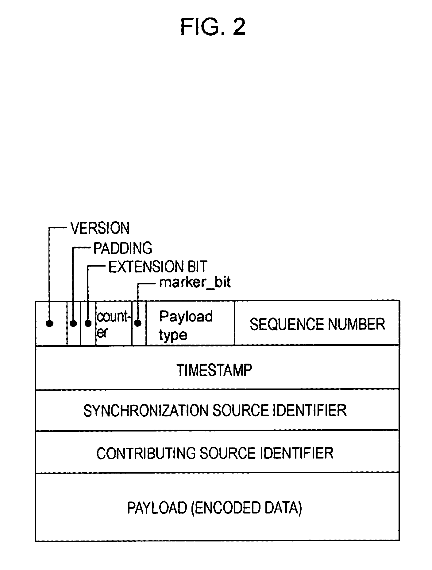
[0039]FIG. 2 shows the configuration of an RTP packet. An RTP header includes, a...


PUM


Abstract

A data communication system includes a data transmitting apparatus and a data receiving apparatus. The data transmitting apparatus includes a packetizing section that generates data packets, an encoding section that performs redundant encoding on the data packets in predetermined time units and generates encoded blocks, a data transmitting section that transmits each encoded block to the data receiving apparatus, a data-size acquiring section that acquires a data size of transmission data in each predetermined time unit, and a packet-size determining section that, on the basis of the acquired data size, in each predetermined time unit, determines a packet size of each data packet. The data receiving apparatus includes a data receiving section that acquires data packets of the transmission data by receiving each encoded block transmitted, and a depacketizing section that analyzes the data packets of the acquired transmission data and reconfigures the transmission data.

Description

CROSS REFERENCES TO RELATED APPLICATIONS[0001]The present invention contains subject matter related to Japanese Patent Application JP 2006-346959 filed in the Japanese Patent Office on Dec. 25, 2006, the entire contents of which are incorporated herein by reference.BACKGROUND OF THE INVENTION[0002]1. Field of the Invention[0003]The present invention relates to a data communication system, a data transmitting apparatus, a data transmitting method, and a method for determining a packet size and redundancy. In particular, the present invention relates to a data communication system in which, when transmission data is packetized and processed by redundant encoding in predetermined time units, and the resultant data is transmitted from a data transmitting apparatus to a data receiving apparatus, by determining a packet size on the basis of a data size of the transmission data in each predetermined time unit, sufficient tolerance for burst loss can be obtained even at a low data rate with...

Claims


Application Information

Patent Timeline
IPC IPC(8): H04L12/26H04L47/43H04L1/00H04L47/36H04N7/173
CPCH04L1/0007H04L1/0009H04L65/608H04L1/0057H04L65/607H04L1/0018H04L65/65H04L65/70H04L47/36H04L1/00
Inventor KURE, YOSHINOBU
Owner SONY CORP
Learn More