Parts washing system

a washing system and part technology, applied in the field of cleaning, can solve the problems of dermatitis and respiratory problems, high disposal costs, and insufficient concentration of mineral spirits, and achieve the effect of not having a toxic effect on users

Inactive Publication Date: 2005-03-17
ZYMO INT +1
View PDF99 Cites 1 Cited by
  • Summary
  • Abstract
  • Description
  • Claims
  • Application Information

AI Technical Summary

Benefits of technology

[0020] Still another object of the present invention is to provide a cleaning system that does not have a toxic effect on users.
[0021] Still another object of the present invention is to provide a parts washing system that does not employ a volatile and flamma

Problems solved by technology

While mineral spirits are an effective cleaning solvent, there are many drawbacks to the employment of parts washers that utilize mineral spirits.
Further, mineral spirits that are not properly contained can have a negative impact on the environment, and it is not uncommon for workers to have dermatitis and respiratory problems exacerbated by unprotected use of mineral spirits.
Additionally, many users of mineral spirits find it necessary to dispose of used mineral spirits by having a waste disposal company pick up the

Method used


Image

  • Parts washing system
  • Parts washing system
  • Parts washing system

Examples


Embodiment Construction

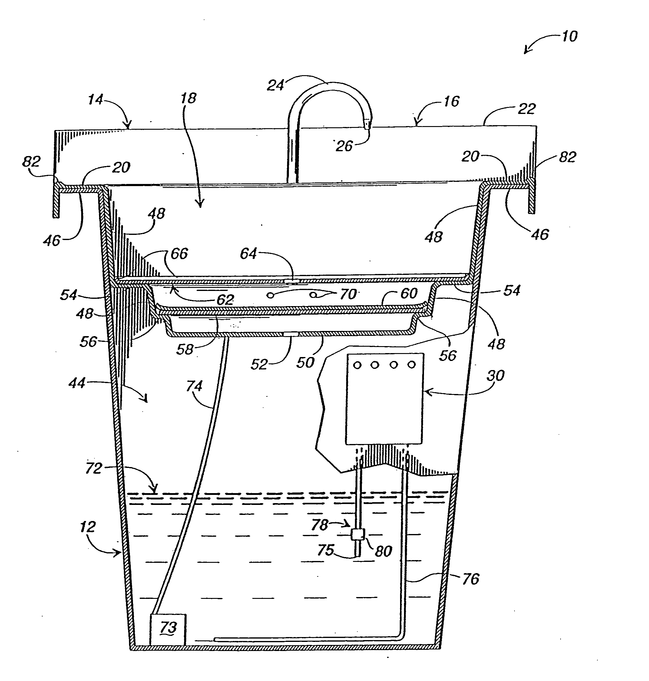
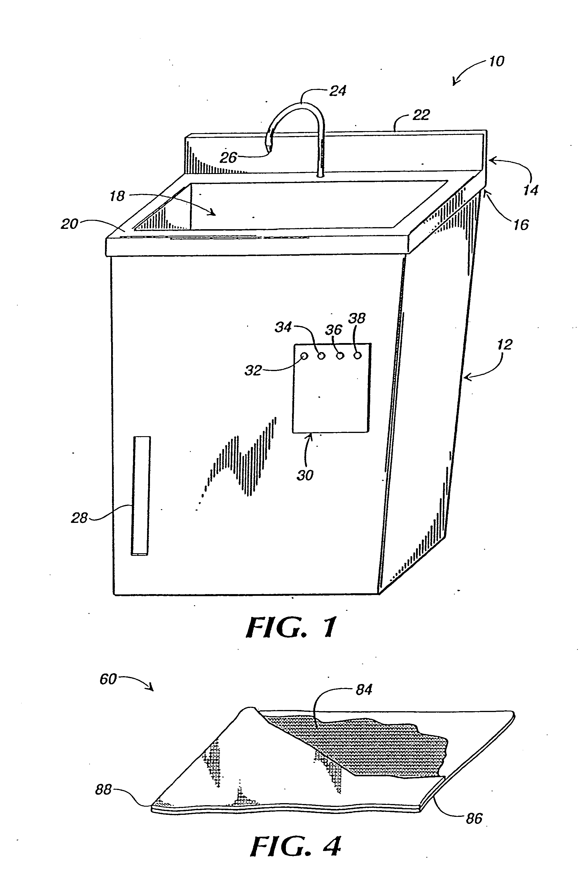
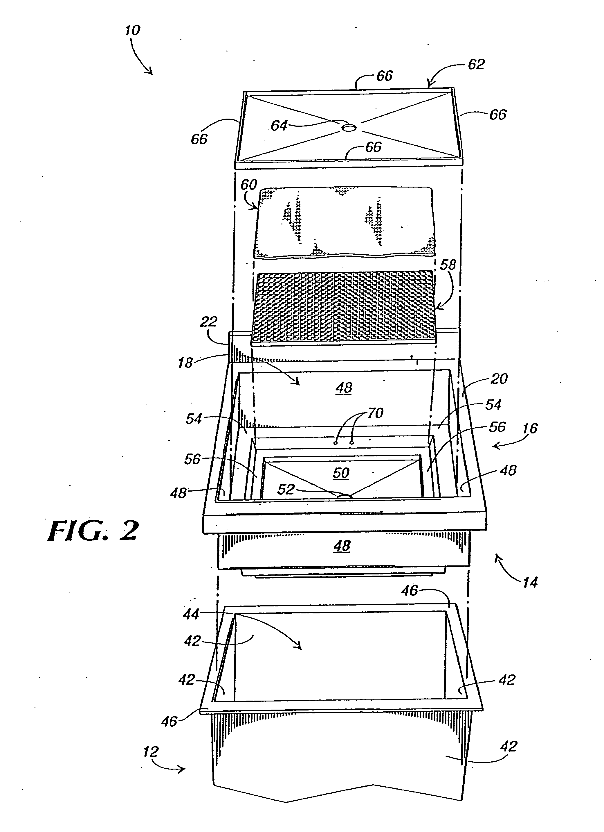
[0027] Referring now in greater detail to the drawings, in which like numerals represent like components throughout the several views, FIG. 1 is an exterior, perspective view of a parts washer apparatus (the “parts washer”) 10, in accordance with the preferred embodiment of the present invention. The parts washer 10 includes a tank 12 and a basin 14. The basin 14 includes a sink member 16 that defines a basin cavity 18. The sink member includes a sink ledge 20 around the periphery of the inlet to the basin cavity 18. A back-splash 22 extends upward from a rear portion of the sink ledge 20, and a flexible faucet 24 penetrates the rear portion of the sink ledge 20 and terminates in the form of a nozzle 26. An optional work light (not shown) extends upward from the basin and illuminates the basin cavity 18. The tank 12 preferably includes a level indicator 28 and a control panel 30. The level indicator 28 is depicted as comprising a temperature sensitive, liquid crystal display. The co...


PUM

PropertyMeasurementUnit
Sizeaaaaaaaaaa
Temperatureaaaaaaaaaa
Flow rateaaaaaaaaaa

Abstract

Provided is a parts washer that includes a multi-tiered basin, a cleaning fluid and a biological component, living within the fluid, that breaks down organic waste. The multi-tiered basin includes a sink member with a false bottom, and a support grid and filter are interposed between the false bottom and a bottom panel of the sink member. The false bottom, support grid, and filter are readily removable from the sink member. The tank is partially filled with the cleaning fluid and a pump and conduit assembly direct a flow of the cleaning fluid to the basin. The cleaning fluid discharged into the basin flows through a drain hole in the false bottom, through the filter and support grid, and then through a drain hole in the bottom panel of the sink member back into the tank for reuse. The cleaning fluid includes, at least, a surfactant that functions to remove organic waste from the parts being washed. The biological component within the cleaning fluid includes nonpathogenic microorganisms that break down the organic waste. The cleaning fluid is not toxic to the microorganisms. The pump and conduit assembly, in addition to aiding in the removal of organic waste, functions to aerate the cleaning fluid to maintain a proper environment for the microorganisms. A heater, thermostat, and level control assembly function to maintain the cleaning fluid within ascertain temperature range so as to aid in the removal of organic waste and maintain a proper environment for the microorganisms.

Description

BACKGROUND OF THE INVENTION [0001] The present invention relates generally to the field of cleaning and more particularly to the field of parts washers. [0002] Parts washers are well known and are often employed in the cleaning of parts that are contaminated with organic waste products such as, for example and not limitation, hydrocarbons, oils, and greases. For background and understanding, the type of parts normally being discussed as washed in a parts washer are, for example, automotive parts such as valves, pistons, transmission parts, covers, and so forth. Most conventional parts washers include a basin mounted to the top of a tank. The tank is partially filled with a mineral spirits solvent that is pumped from the tank through a conduit that discharges into the basin where the parts are washed. The mineral spirits solvent drains from the basin back to the tank for reuse. A filter is sometimes interposed in the solvent flow path to collect organic waste products and particulate...

Claims


Application Information

Patent Timeline
IPC IPC(8): B08B3/00B08B7/00B08B7/04C02F3/04C02F3/10C02F3/34C12P1/00C12S9/00
CPCB08B3/006B08B7/00B08B2203/007C02F3/04C02F3/10C02F3/34C12P1/00C02F3/343C02F3/344C02F2103/44C12R1/00C12N1/00C12R2001/00Y02W10/10
Inventor MCCLURE, JAMES C.MCNALLY, THOMAS W.MARKS, FRANCIS A.STRANGE, J. LELAND
Owner ZYMO INT
Why Eureka
Try Eureka