
Tracked vehicle with improved track drive unit

a track drive and track technology, applied in the direction of mechanical control devices, instruments, hoisting equipment, etc., can solve the problems of premature failure of track elements, and substantial deflection of track on opposite sides of the guide wheel, so as to improve the traction and improve the traction. , the effect of improving the wear of the track

Inactive Publication Date: 2005-03-17
TUCKER SNO CAT CORP
View PDF41 Cites 29 Cited by
  • Summary
  • Abstract
  • Description
  • Claims
  • Application Information

AI Technical Summary

Benefits of technology

[0011] There is a need for an improved drive track unit for endless track-driven vehicles, and especially for four-tracked vehicles and such vehicles that carry heavy loads, that will overcome the foregoing problems. It is therefore a general object of the present invention to provide a track-driven vehicle that overcomes the foregoing problems and provides improved traction, improved track wear, and less terrain disturbance than prior such vehicles, especially when carrying heavy loads.
[0012] Another object of the invention is to provide an improved drive track unit for an all-terrain vehicle that is especially suited for heavy vehicles, and provides a better load distribution to the drive track than prior such assemblies, thereby reducing track damage and wear, and consequential ground disturbance during use, and improving vehicle traction, while reducing the likelihood of track bounce or track jump.
[0013] A further object of the invention is to provide an improved guide wheel assembly for the drive track unit of a tracked vehicle that provides a better load distribution to the drive track than prior such assemblies by mounting separate guide wheel units of the assembly on opposite sides of a carrier beam of the drive track unit, thereby distributing the vehicle load across substantially the full width of the drive track, to reduce drive track damage and wear, and terrain disturbance, and improve vehicle traction.

Problems solved by technology

Although this system, with a single line or row of guide wheels, functioned adequately, it was found that substantial deflection of the track on opposite sides of the guide wheels was occurring.
This could lead to premature failure of elements in the track due to high cyclical stresses.
This same high-point loading of the track and its consequential deflection could also lead to premature failure of the track and reduce its effective traction.
In the case of sensitive terrain such as tundra, such loading could cause excessive damage to the terrain, especially with the endless track usually including traction bars or cleats on its outer surface for enhancing the vehicle's traction.
Consequently, some of the track wear and terrain disturbance problems still occurred, especially with all-terrain vehicles that carry heavy loads.
Therefore, each such single three-wheel guide wheel assembly still left extensive outwardly and inwardly extending track surface areas across the width of the track unsupported on the lower track run.
Accordingly, substantial track deflection and wear could still occur, as could substantial damage to sensitive terrain underlying the track area.
Another problem with the guide wheel assemblies of the track units of U.S. Pat. No. 6,129,426, was that such guide wheel assemblies were not provided throughout the entire lower track run of the track unit.
Heretofore, such drive sprocket wheel assemblies have been expensive to fabricate and assemble because of their multiple separate parts.
The resulting drive wheel assembly was also quite heavy and, especially when used in multiples in a four-tracked vehicle, added substantial weight to the vehicle, thereby increasing the loading of its often already heavily loaded drive tracks.
However, such cleats tend to exacerbate the ground disturbance problems arising from point- or concentrated loading of the belts by the guide wheels of such units.
Another problem that can arise with drive track units that support heavy loads and utilize rubber drive belts, is that the belts may stretch or “give” in use especially when high driving forces are applied by a sprocket wheel to the drive lugs of the belt.
Such stretch can give use to so-called track bounce creating heavy vehicle vibrations, or even track jump, where the belt lugs jump from engagement with the sprocket drive cogs, causing the vehicle to lose power.

Method used


Image

  • Tracked vehicle with improved track drive unit
  • Tracked vehicle with improved track drive unit
  • Tracked vehicle with improved track drive unit

Examples


Embodiment Construction

[0030] To provide a comprehensive disclosure without unduly lengthening the specification, applicant incorporates herein by reference the disclosures of U.S. Pat. Nos. 6,129,426, 6,007,166, 3,787,099, and 3,857,616.

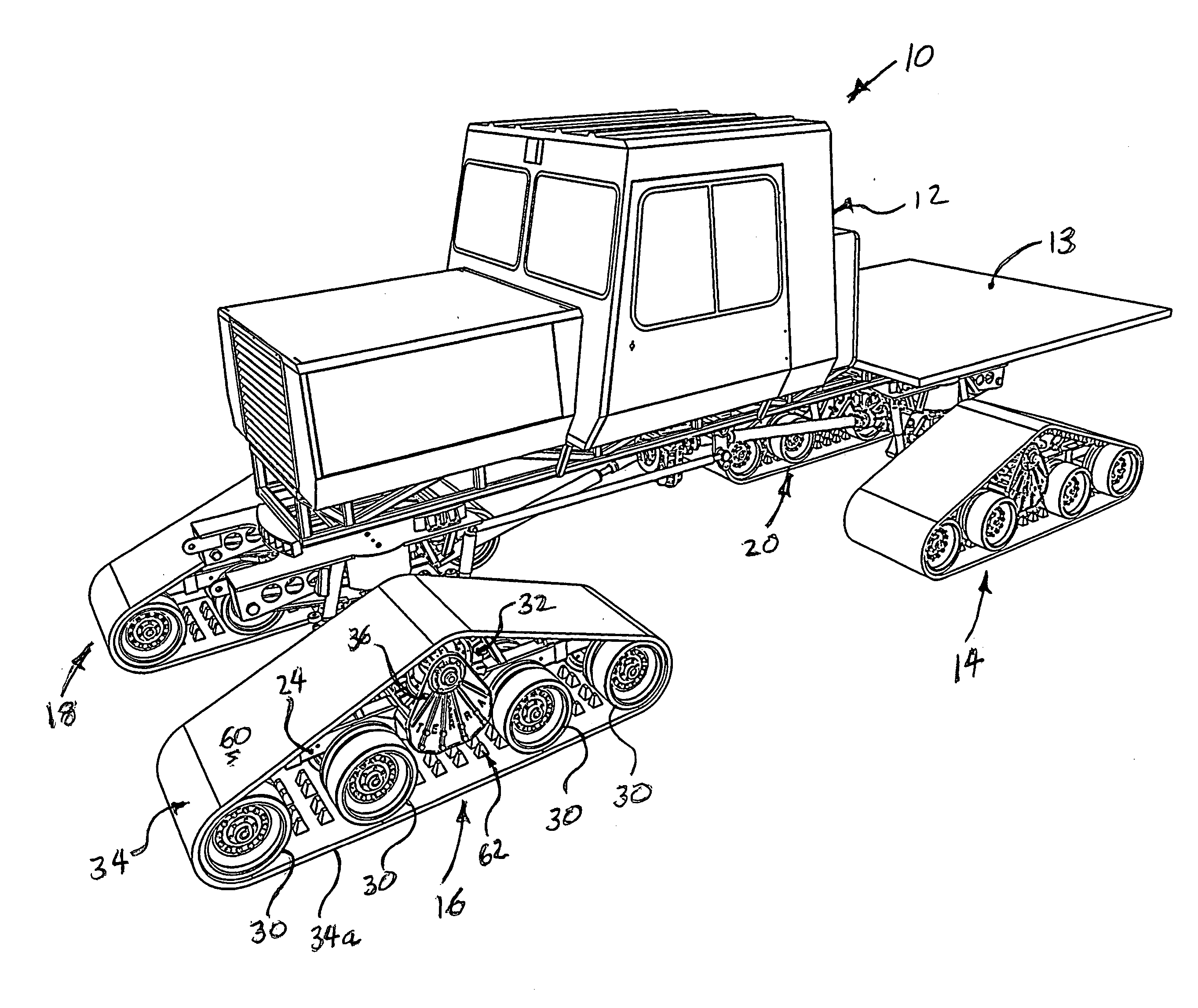
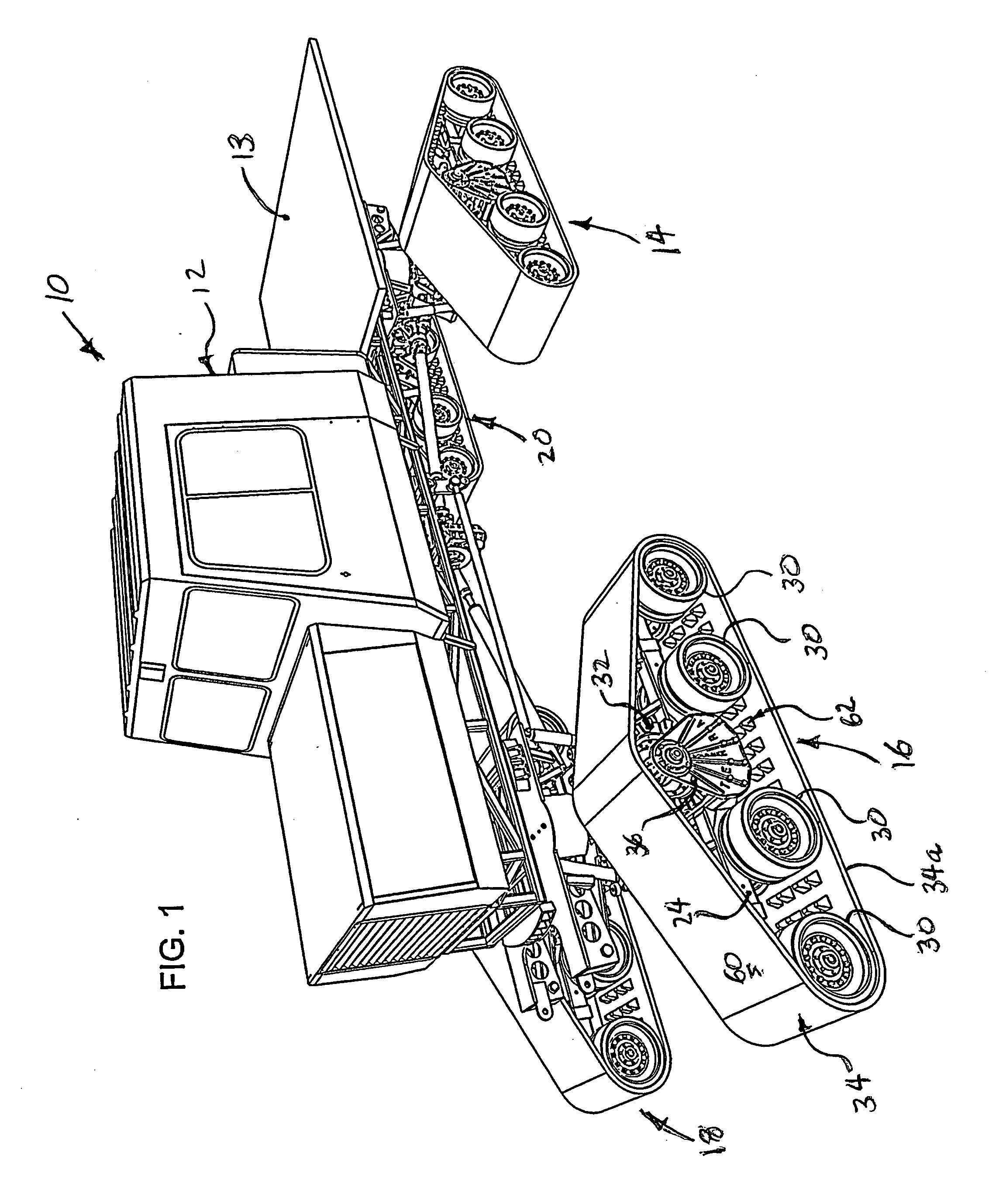
[0031] Referring first to FIG. 1, a four-track all-terrain vehicle 10 has a vehicle body 12 supported by four identical endless drive track units 14, 16, 18, and 20, respectively. Track units 14 and 20 are mounted at opposite sides of the rear of the vehicle, and track units 16, 18 are mounted at opposite sides of the front of the vehicle. Each drive track unit is independently mounted, driven, and steerable in a well-known manner. At the forward end of the vehicle, a snow plow, grader blade, or a variety of other attachments (not shown) may be mounted. Similarly, various attachments may be mounted at the rear end of the vehicle, all for multiple operations over a variety of terrain. The particular vehicle shown includes a load platform 13.

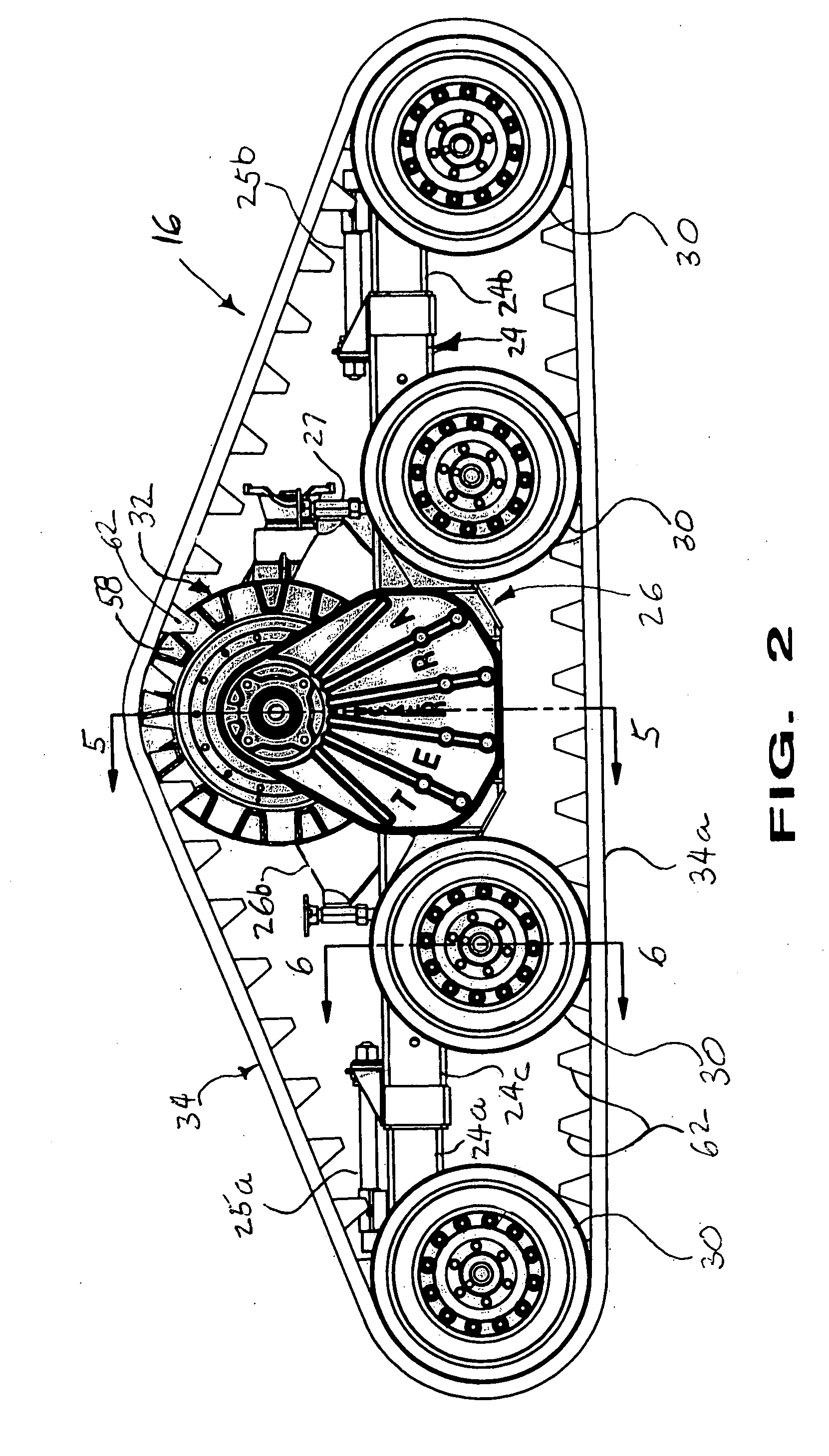
[0032] Referring to FIGS. 2-6,...


PUM


Abstract

An all-terrain vehicle is supported and driven by endless track units. Each track unit includes a drive belt with rows of interior drive lugs driven by cogs on multiple sprocket wheels of a common drive wheel assembly having an integrated, one-piece drum and hub. Multiple guide wheel assemblies engaging the lower run of the drive belt distribute the vehicle load across substantially the full width of the belt. Each guide wheel assembly includes a pair of guide wheel units mounted on opposite end portions of a common spindle and on opposite sides of a carrier beam of the track unit. Each guide wheel unit has a wide belt-engaging surface extending to, or close to, an edge portion of the belt and interrupted by an annular groove permitting passage of a row of the belt drive lugs while maintaining alignment of the belt and drive wheel assembly.

Description

FIELD OF THE INVENTION [0001] The present invention relates to all-terrain tracked vehicles, and more particularly to an improved endless drive track unit for such tracked vehicles. BACKGROUND OF THE INVENTION [0002] Endless track-driven vehicles are commonly used off-road in difficult terrain and under difficult terrain conditions, such as in mud, snow, sand, and tundra. For example, tracked vehicles are used in snow country for grooming ski slopes and snow mobile trails, for transporting skiers to back-country slopes, for ski resort maintenance work, and for snow and mountain rescue. They are also used in various types of terrain for utility company maintenance work, and for oil exploration and oil pipeline maintenance in arctic tundra. [0003] Tracked vehicles are generally of two types. Many are two-tracked in which a pair of endless drive track units, one on each of the opposite sides of the vehicle, support and drive the vehicle. Others are four-tracked, in which four separatel...

Claims


Application Information

Patent Timeline
Patent Type & Authority Applications(United States)
IPC IPC(8): B62D55/065B62D55/125B62D55/14B62D55/24
CPCB62D55/065B62D55/244B62D55/14B62D55/125
Inventor TUCKER, JASPER JAMES
Owner TUCKER SNO CAT CORP
Learn More