Welding state detecting and transmitting device for resistance-welding machine

a technology of transmitting device and welding state, which is applied in the direction of welding monitoring device, welding apparatus, manufacturing tools, etc., can solve the problems of troublesome physical access to the welding state transmitting device attached to the secondary side, loss of advantages of the second prior art for wirelessly transmitting data to the external device, and troublesome replacement of batteries or recharging batteries within the device, etc., to achieve the effect of reducing the burden of maintenance operations and easy to obtain

Inactive Publication Date: 2005-03-17
NA DETSUKUSU
View PDF2 Cites 7 Cited by
  • Summary
  • Abstract
  • Description
  • Claims
  • Application Information

AI Technical Summary

Benefits of technology

[0012] The first object of the present invention is to substantially reduce the burden of maintenance operations of the welding state detecting and transmitting device, such as replacing the primary battery, recharging the secondary battery, changing detecting conditions, changing transmitting conditions, or rewriting operating program, etc. of the welding state detecting and transmitting device.
[0027] The present device eliminates the necessity of troublesome maintenance operations, such as physically accessing to the device attached to the secondary side of the resistance-welding machine, removing the device from the secondary side and rewriting the operating programs. Consequently, the burden of maintenance of the operating programs for the device can be substantially reduced.

Problems solved by technology

If the welding state detecting and transmitting device of the second prior art is connected to a commercial power source or the like means by an electrical cable for obtaining electric driving power from the commercial power source or the like means, the advantages of the second prior art for wirelessly transmitting data to the external device are lost.
Consequently, physically accessing to the welding state detecting and transmitting device attached to the secondary side is troublesome.
Replacing batteries or recharging batteries within the device is also troublesome.
Accessing physically by the operator to the welding state detecting and transmitting device attached to the secondary side of the resistance-welding machine is troublesome.
Therefore, maintenance operations, such as changing detecting conditions, changing transmitting conditions, or rewriting operating program constitute a considerable burden.

Method used


Image

  • Welding state detecting and transmitting device for resistance-welding machine
  • Welding state detecting and transmitting device for resistance-welding machine
  • Welding state detecting and transmitting device for resistance-welding machine

Examples


first embodiment

[0033] (First Embodiment)

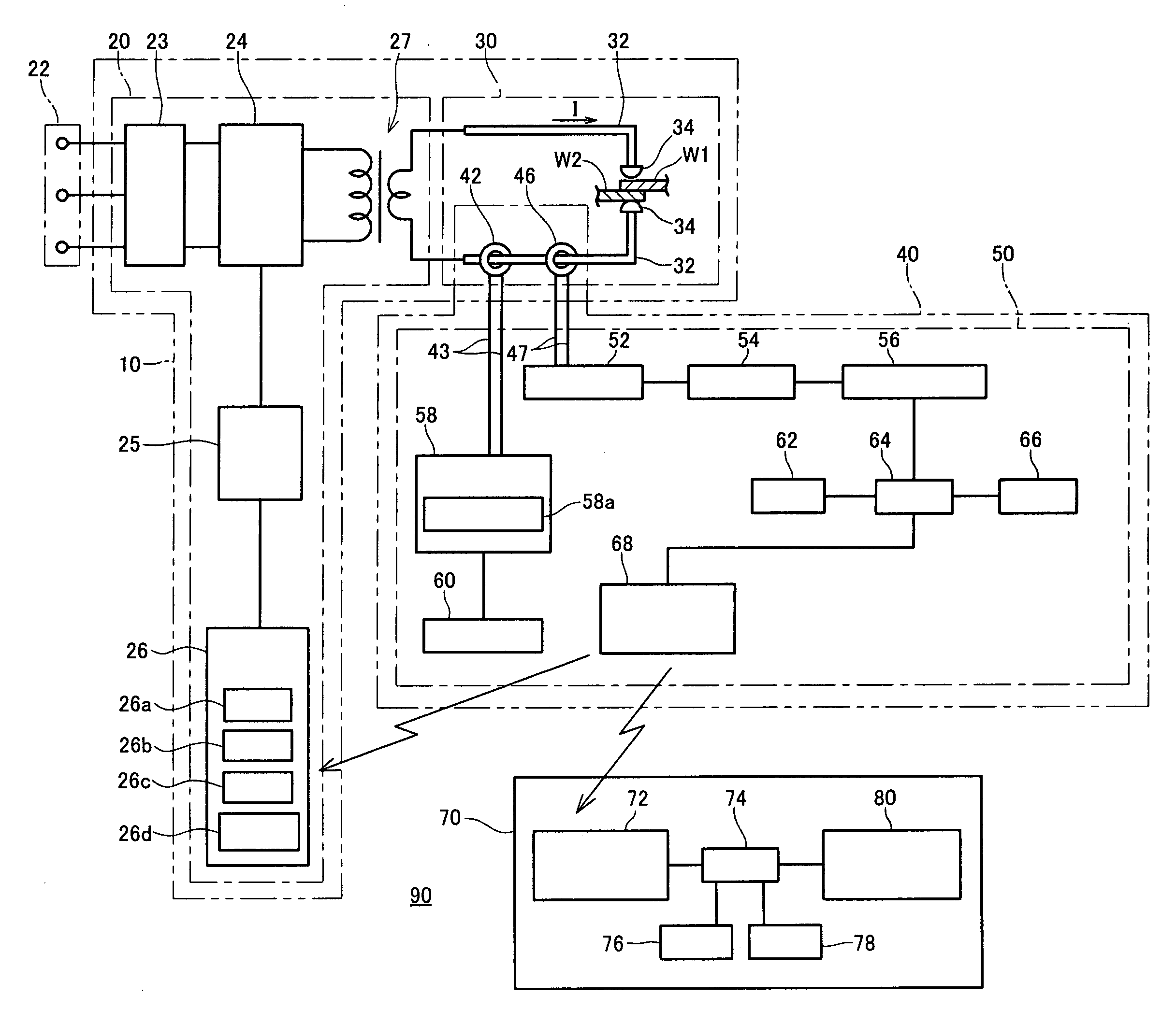
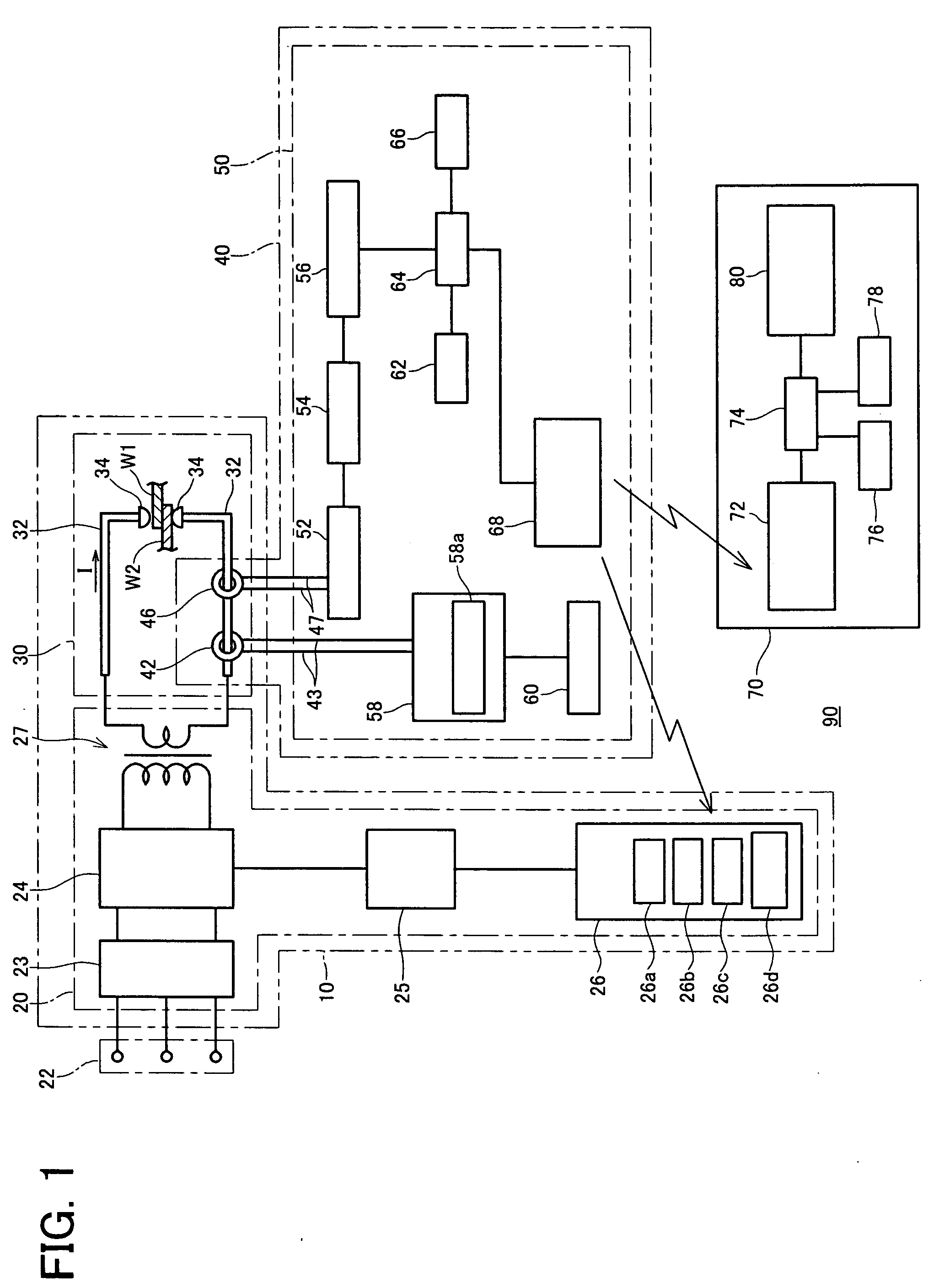
[0034]FIG. 1 is an explanatory view showing a welding state detecting and transmitting device 40 of a first embodiment, and a welding state detecting system 90. The system 90 is provided with a resistance-welding machine 10, the welding state detecting and transmitting device 40, and an external device 70 for receiving data from the device 40, storing the received data, processing the received data, storing the processed data, and outputting the received and the processed data.

[0035] The resistance-welding machine 10 is provided with a circuit unit 20 and a welding gun unit 30. The circuit unit 20 is provided with a commutating circuit 23, an inverter circuit 24, and a transformer 27, these being connected in sequence. The commutating circuit 23 is connected with a commercial three-phase alternating current source 22. The circuit unit 20 is further provided with a driving circuit 25 connected with the inverter circuit 24, and a welding state controlling dev...

second embodiment

[0062] (Second Embodiment)

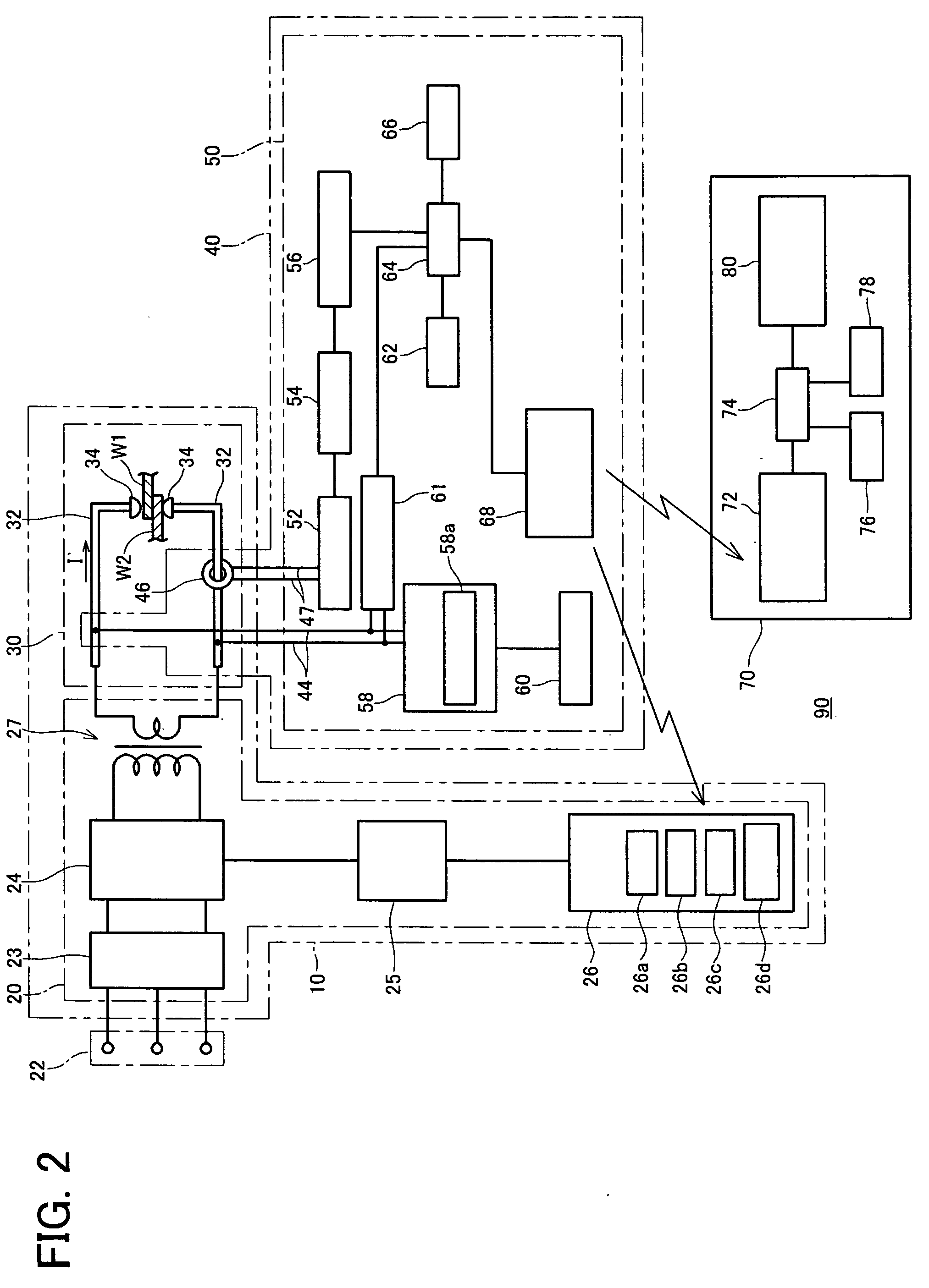
[0063]FIG. 2 is an explanatory view showing a welding state detecting and transmitting device 40 and a welding state detecting system 90 of a second embodiment.

[0064] In this system, a pair of cables 44 is connected with a charging circuit 58 of the device 40. Each of the pair of cables 44 is connected with one of the pair of secondary side conductors 32. Further, the pair of cables 44 bifurcates and is connected with an A / D conversion circuit 61. The A / D conversion circuit 61 is connected with a CPU 64. By this means, voltage data originating from the pair of secondary side conductors 32, 32 can be detected, processed, and analyzed, etc. These points are the main differences of the second embodiment from the first embodiment.

[0065] In addition to the functions described above, the welding state detecting and transmitting device 40 of the first or second embodiments also has the following effects.

[0066] (1) By using the charging toroidal coil 42 (first e...


PUM

PropertyMeasurementUnit
electric poweraaaaaaaaaa
voltageaaaaaaaaaa
pressureaaaaaaaaaa

Abstract

The welding state detecting and transmitting device 40 is provided with a secondary battery 60 for accumulating power to be supplied to components within the device 40, a charging circuit 58 that utilizes a portion of the welding current to charge the secondary battery 60. A toroidal coil 42 is used for charging the secondary battery 60 with welding current. The troidal coil 42 is attached to secondary side conductor 32 and connected with the charging circuit 58. The device 40 wirelessly transmits data relating to the welding current detected by the toroidal coil 46. The device 40 substantially reduces the burden of maintenance of the device 40 required in prior art such as replacing a primary battery or recharging a rechargeable battery periodically.

Description

FIELD OF THE INVENTION [0001] The present invention relates to a device for detecting welding state indices such as welding current, welding pressure, welding time (including indices relating thereto), etc. of a resistance-welding machine, and for wirelessly transmitting data to an external device based on the detected indices. BACKGROUND OF THE INVENTION [0002] A welding state detecting and recording device is known to the art. The known device is provided with a toroidal coil for detecting indices relating to welding current of a resistance-welding machine, and a data storing means for storing data based on the indices detected by the toroidal coil. The toroidal coil and the data storing means are connected by a long cable (first prior art). [0003] Further, Japanese Laid Open Patent Publication (TOKKAIHEI) 8-99181 discloses a welding state detecting and transmitting device. The device is utilized after being attached to a secondary side of a resistance-welding machine. The welding...

Claims


Application Information

Patent Timeline
Patent Type & Authority Applications(United States)
IPC IPC(8): B23K11/25
CPCB23K11/257
Inventor NIWA, KAZUHIKO
Owner NA DETSUKUSU
Why Eureka
Try Eureka