Perpendicular magnetic head and method for manufacturing the same

a technology of perpendicular magnetic recording and manufacturing method, which is applied in the manufacture of head surface, instruments, and record information storage, etc., can solve the problems of distorted magnetic data or record signals, inaccurate recording, and noise during reproduction of recorded signals, so as to prevent side fringing and erasure of recorded signals. , the effect of low nois

Inactive Publication Date: 2005-03-17
TDK CORPARATION
View PDF2 Cites 61 Cited by
  • Summary
  • Abstract
  • Description
  • Claims
  • Application Information

AI Technical Summary

Benefits of technology

[0030] Accordingly, an object of the present invention is to provide a perpendicular magnetic recording head including a primary magnetic pole having a flat top surface and an integrated shield layer including side shields disposed at both sides of the primary magnetic pole and an upper shield disposed over the magnetic pole, and a method for manufacturing the perpendicular magnetic recording head. The magnetic recording head having such structure exhibits low noise, and prevents side fringing and erasure of recorded signals.

Problems solved by technology

If the top surface of the primary magnetic pole is not flat and is formed in curved manner or convex shape, magnetic data or record signals are distorted and recorded inaccurately.
Consequently, noise occurs during reproduction of the recorded signals.

Method used


Image

  • Perpendicular magnetic head and method for manufacturing the same
  • Perpendicular magnetic head and method for manufacturing the same
  • Perpendicular magnetic head and method for manufacturing the same

Examples


first embodiment

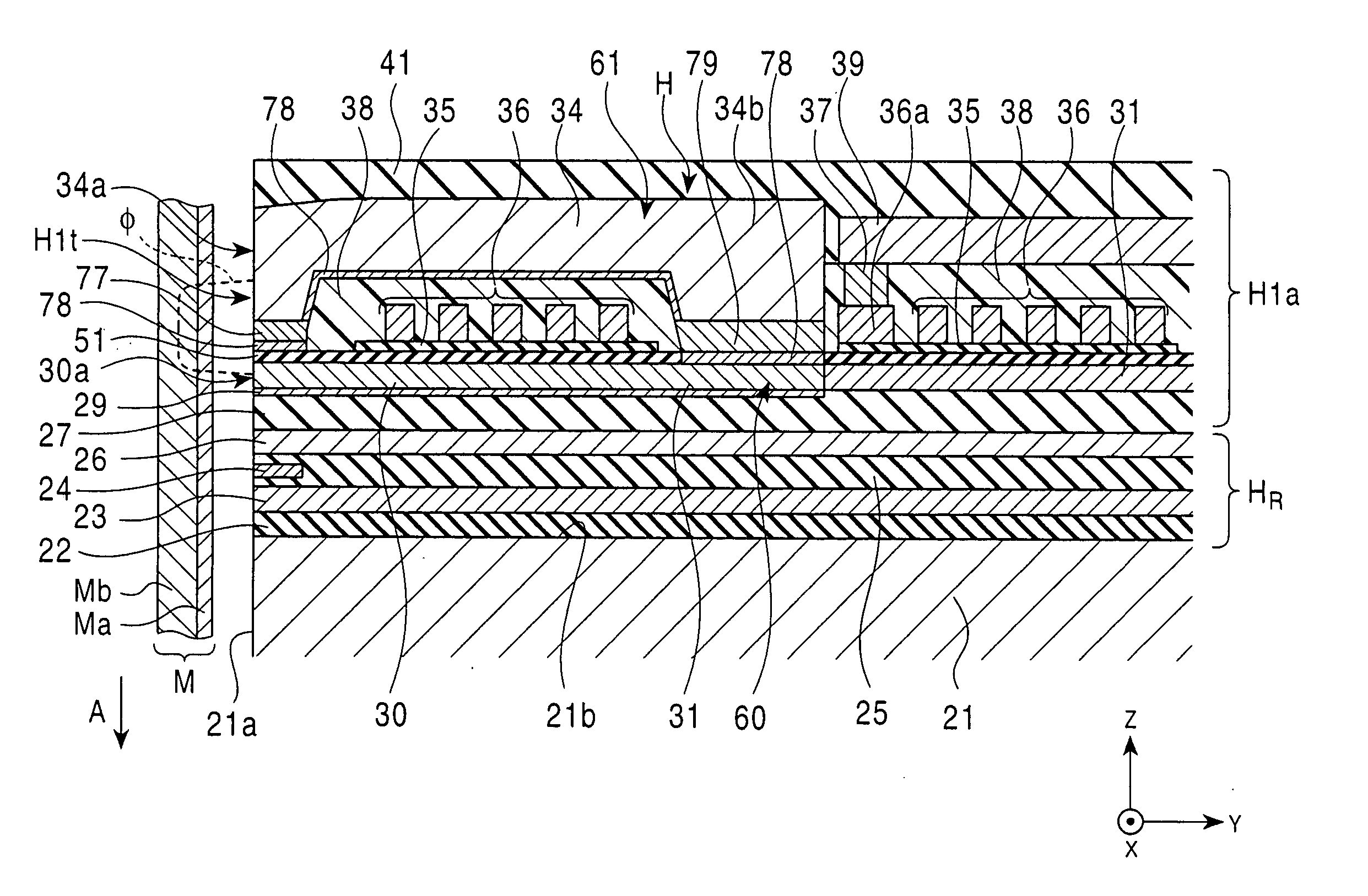
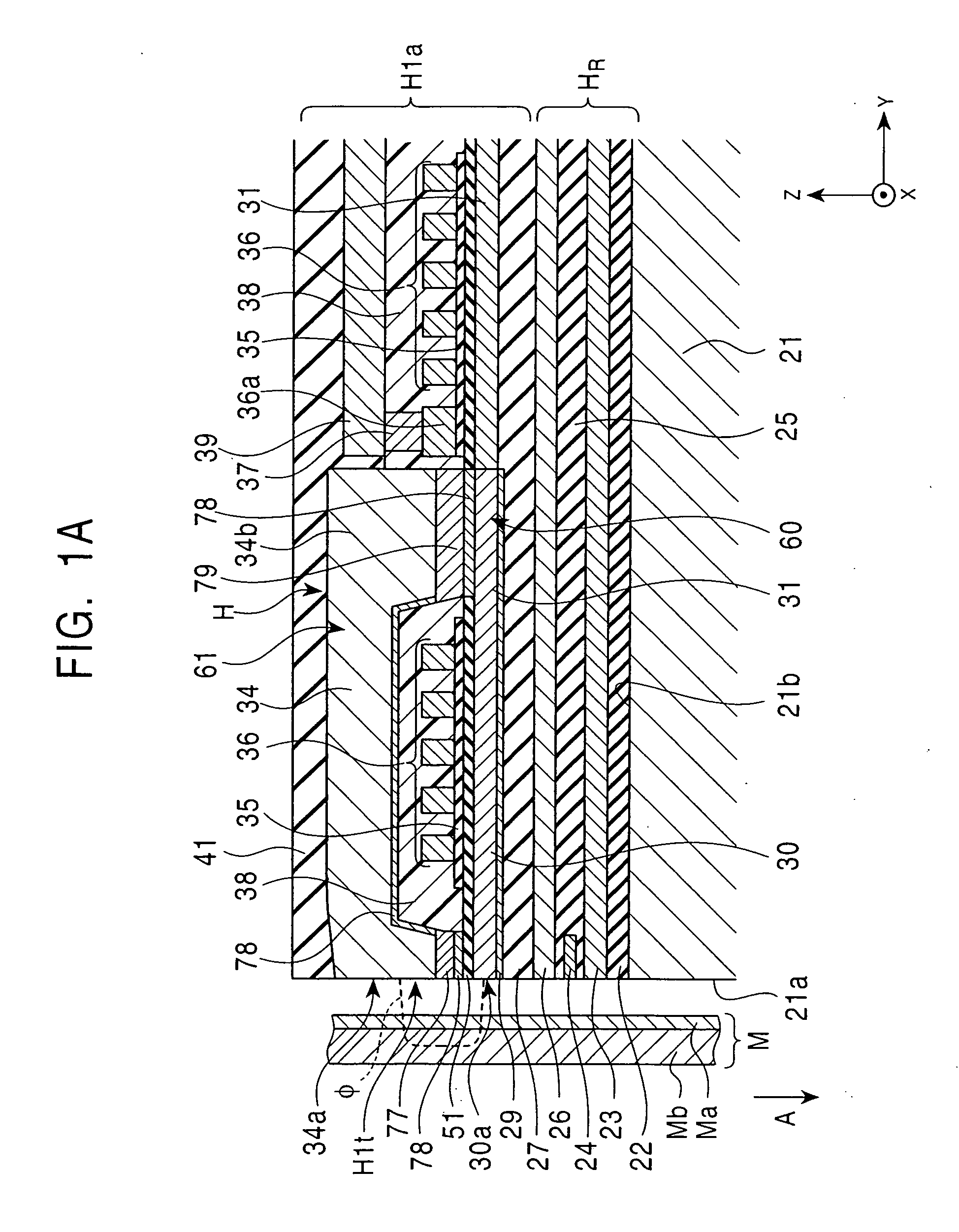
[0115]FIG. 1A is a longitudinal sectional view of a perpendicular magnetic recording head H1a according to the present invention, and FIG. 2 is a front view of the magnetic head H1a shown in FIG. 1A. The section of FIG. 1A is taken along line IA-IA of FIG. 2 and viewed from the direction indicated by the arrow. FIG. 3 is a fragmentary schematic perspective view of the perpendicular magnetic recording head H1a shown in FIG. 1A.

[0116] The perpendicular magnetic recording head H1a applies a perpendicular magnetic field to a recording medium M to magnetize a hard layer Ma of the medium M in the perpendicular direction.

[0117] The recording medium M is, for example, a disk including the hard layer Ma having high residual magnetization at its surface and a soft layer Mb having a high magnetic permeability inside. The disk rotates on its center.

[0118] A slider 21 is made of a nonmagnetic material, such as Al2O3—TiC, and its one side surface 21a opposes the recording medium M. Rotation of ...

second embodiment

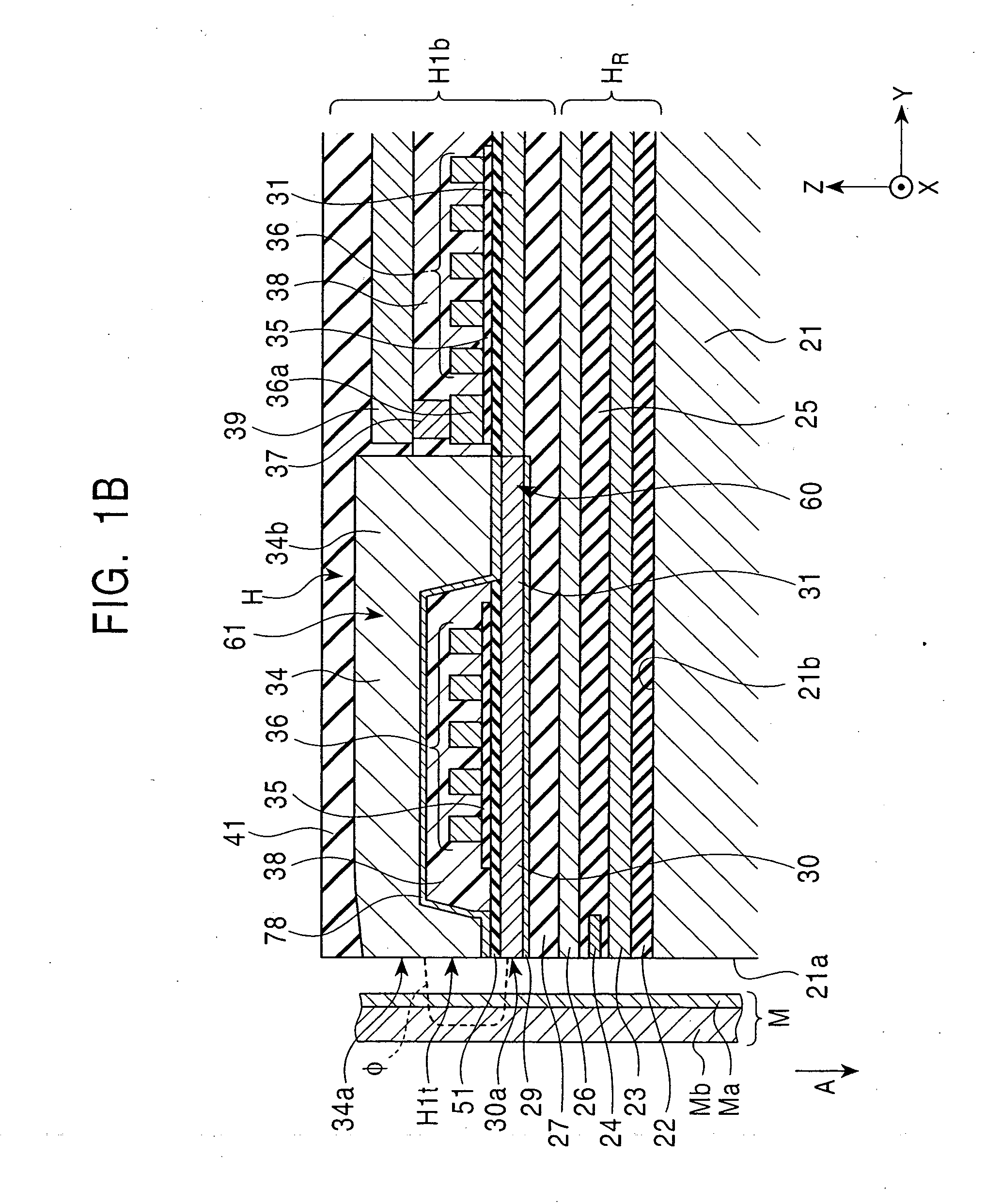
[0149]FIG. 4 is a front view of a perpendicular magnetic recording head H2 according to the present invention, and corresponds to FIG. 2.

[0150] The same reference numerals as in the perpendicular magnetic recording head H1a shown in FIG. 2 designate the same parts.

[0151] The perpendicular magnetic recording head H2 shown in FIG. 4 has a shield bank layer 80 made of a nonmagnetic material with a predetermined distance L1 from the side surface of the primary magnetic pole 30 on the first nonmagnetic material layer 50. The shield bank layer 80 is made of at least one inorganic insulating material selected from among Al2O3, AlSiO, and AlSiON. Accordingly, the distance between the shield layer 77 or the secondary magnetic pole 34 and the upper shield layer 26 of the reading portion HR is increased by the thickness t1 of the shield bank layer 80. Thus, the insulation between the shield layer 77 or the secondary magnetic pole layer 34 and the upper shield layer 26 of the reading portion H...


PUM

PropertyMeasurementUnit
widthaaaaaaaaaa
widthaaaaaaaaaa
widthaaaaaaaaaa

Abstract

A perpendicular magnetic recording head includes a primary magnetic pole having a flat top surface. The magnetic head also includes a shield layer over the primary magnetic pole and at the sides of the primary magnetic pole in a single piece. The distance in the direction perpendicular to the thickness direction between the side surfaces of the primary magnetic pole and the side shield layer is longer than the distance in the thickness direction between the top surface of the primary magnetic pole and the shield layer.

Description

BACKGROUND OF THE INVENTION [0001] 1. Field of the Invention [0002] The present invention relates to perpendicular magnetic recording heads which apply a perpendicular magnetic field to a recording medium, such as a disk with a hard layer, to record data on the medium. In particular, the invention relates to a perpendicular magnetic recording head including a primary magnetic pole having a flat top surface and an integrated shield layer including side shields disposed at the sides of the primary magnetic pole and an upper shield disposed over the primary magnetic pole, and to a method for manufacturing the perpendicular magnetic recording head. The magnetic recording head having such a structure exhibits low noise, and prevents side fringing and erasure of recorded signals. [0003] 2. Description of the Related Art [0004] Perpendicular magnetic recording is one of the techniques for high-density recording of magnetic data on a recording medium, such as a disk. Perpendicular magnetic ...

Claims


Application Information

Patent Timeline
Patent Type & Authority Applications(United States)
IPC IPC(8): G11B5/127G11B5/31
CPCG11B5/1272Y10T29/49043Y10T29/49052Y10T29/49041Y10T29/49046
Inventor YAZAWA, HISAYUKIKOBAYASHI, KIYOSHI
Owner TDK CORPARATION
Why Eureka
Try Eureka