Digital transmission system and clock reproducing device

a transmission system and clock technology, applied in the field of digital transmission systems, can solve the problems of complicated transmission system configuration, inability to change the vco oscillation frequency range immediately on the receiving side, and complicated configuration of the transmission system

Inactive Publication Date: 2005-03-17
SONY CORP
View PDF9 Cites 12 Cited by
  • Summary
  • Abstract
  • Description
  • Claims
  • Application Information

AI Technical Summary

Benefits of technology

It is accordingly an object of the present invention to make it possible to change the VCO oscillation frequency range of the audio clock reproducing PLL on the receiving side immediately and correctly in response to a change in the audio sampling frequency without transmitting information representing the audio sampling frequency as information for locking the audio clock reproducing PLL on the receiving side from the transmitting side to the receiving side, and thus reliably reproduce the audio clock of the frequency corresponding to the audio sampling frequency.

Problems solved by technology

This complicates the configuration of the transmission system.
However, while this method directly transmits a pixel clock (reference clock) for video data as a clock for data processing, it does not directly transmit a clock for audio data, that is, an audio clock, and instead transmits information representing a frequency dividing ratio between the pixel clock and the audio clock.
This, however, requires not only the other transmitting means but also an encoder and a decoder on the transmitting side and the receiving side for the information representing the audio sampling frequency fs, thus complicating the configuration of the transmission system.
A problem therefore occurs in that even when the signal source of the audio signal is changed on the transmitting side and thus the audio sampling frequency fs and the frequency dividing ratios M and N are changed, the VCO oscillation frequency range cannot be changed immediately on the receiving side.
Another problem occurs when the information representing the audio sampling frequency fs does not correspond to the audio data being transmitted because of an encoding error on the transmitting side or the like and thus the audio clock corresponding to the audio data transmitted cannot be obtained.

Method used


Image

  • Digital transmission system and clock reproducing device
  • Digital transmission system and clock reproducing device
  • Digital transmission system and clock reproducing device

Examples


Embodiment Construction

[Embodiment of Digital Transmission System: FIG. 1]

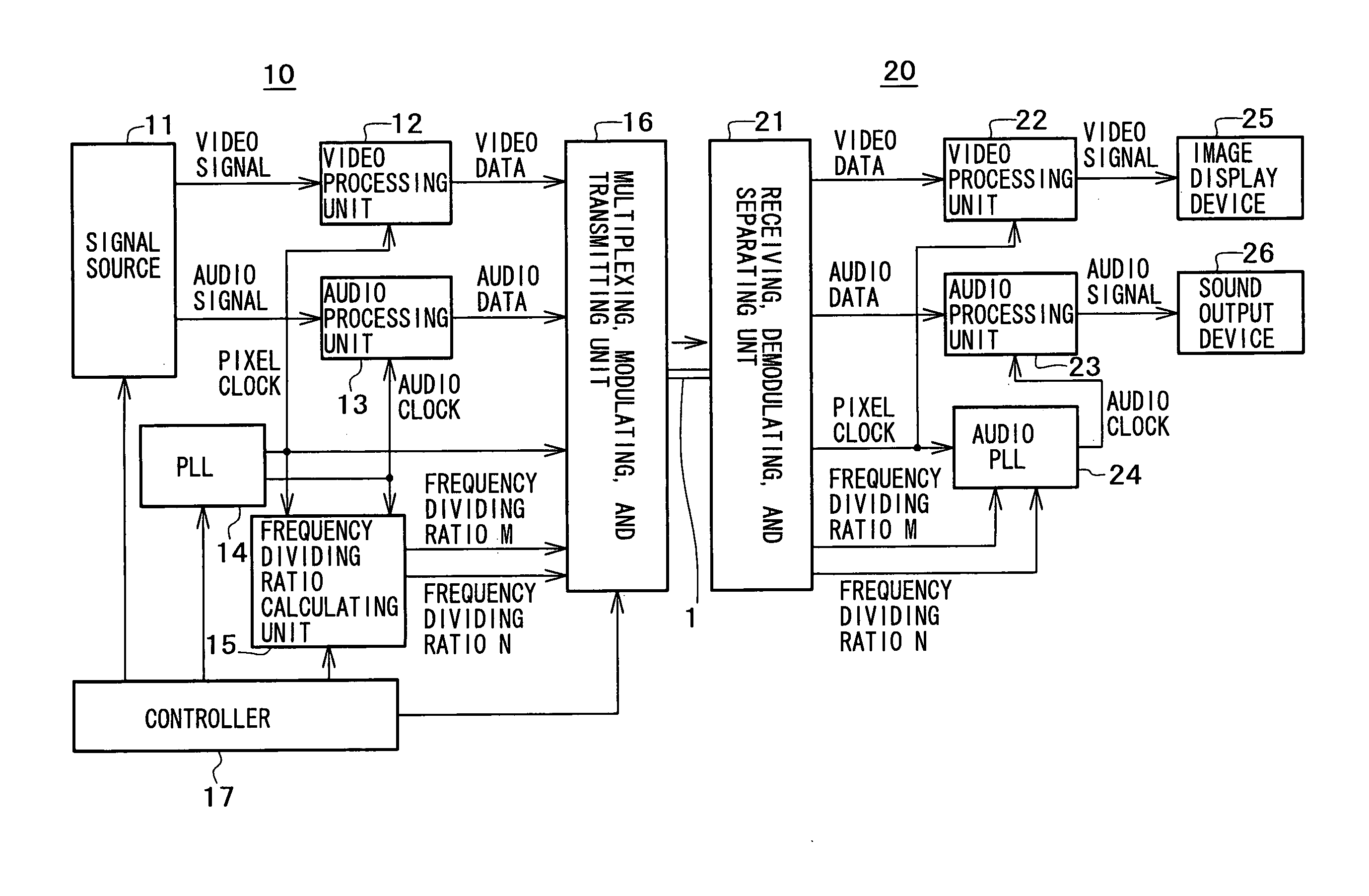
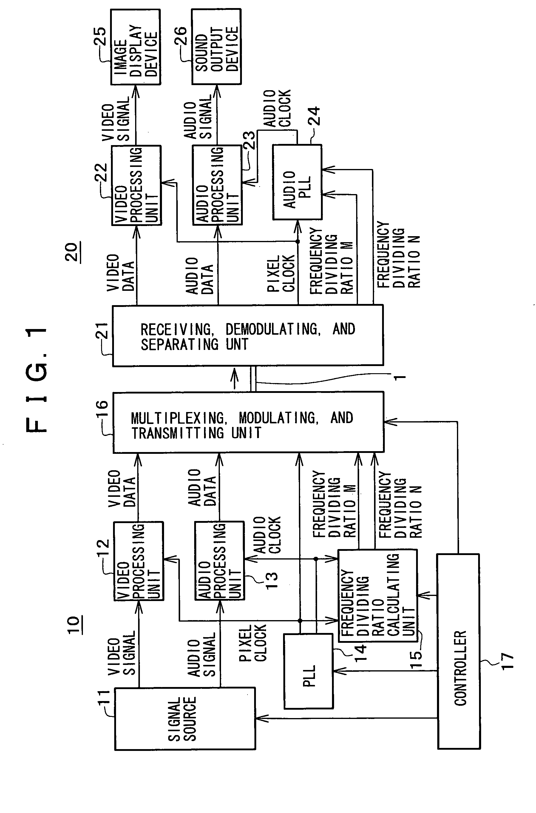
FIG. 1 shows an embodiment of a digital transmission system according to the present invention.

In the digital transmission system according to the present embodiment, a video signal and an audio signal are obtained from a signal source 11 of a transmitting side 10. The signal source 11 is, for example, a TV (television) tuner, a personal computer, or a device for reproducing a video signal and an audio signal from a recording medium, such as an optical disk, a magnetic tape or the like. There may be the same signal source 11 or separate signal sources 11 for the video signal and the audio signal.

The video signal obtained from the signal source 11 is processed by a video processing unit 12 on the basis of a pixel clock from a PLL 14, whereby video data after the processing is obtained from the video processing unit 12. The pixel clock frequency fp is 27 MHz, for example. The video data after the processing is digitized in pixel ...


PUM

PropertyMeasurementUnit
frequency fpaaaaaaaaaa
frequency faaaaaaaaaaa

Abstract

Letting fp be the frequency of a pixel clock, fs be the audio sampling frequency, and fa be the frequency of an audio clock to be reproduced, fa=384fs=(N/M)fp, where N and M are frequency dividing ratios between the pixel clock and the audio clock of a frequency corresponding to the audio sampling frequency. When fs=48 kHz, M=27000 and N=18432, and when fs=44.1 kHz, M=30000 and N=18816. A VCO control unit detects a change in the audio sampling frequency fs from a control voltage Vctl output from a loop filter or from the frequency fo of an output clock of an oscillating unit, and then selects one of at least two VCOs.

Description

CROSS-REFERENCE TO RELATED APPLICATIONS The present application claims priority from Japanese Application No. 2003-295257 filed Aug. 19, 2003, the disclosure of which is hereby incorporated by reference herein. BACKGROUND OF THE INVENTION The present invention relates to a digital transmission system in which audio data and content data, such as video data and the like other than the audio data, are transmitted from a transmitting side to a receiving side and then processed on the receiving side, and a device for reproducing an audio clock, which device is provided on the receiving side of the digital transmission system. A standard referred to as a DVI (Digital Video Interface) standard has been considered as a standard for transmitting a video signal from a signal source, such as a video disk reproducing device, a video tape reproducing device, or a personal computer, as digital video data. In this DVI standard, a video signal is transmitted as data digitized in pixel units fo...

Claims


Application Information

Patent Timeline
Patent Type & Authority Applications(United States)
IPC IPC(8): H04N5/04G11B20/10G11B20/14H03L7/087H03L7/099H03L7/10H03L7/18H04J3/06H04L7/033H04N5/60H04N7/08H04N7/081H04N7/62H04N21/41H04N21/43
CPCH03L7/087H03L7/099H03L7/10H03L7/113H04N21/4305H03L2207/06H04J3/0685H04N5/602H04N21/4122H03L7/18H04N5/04
Inventor MIYAMOTO, MASARU
Owner SONY CORP
Why Eureka
Try Eureka