Surround sound positioning tower system and method

a positioning tower and surround sound technology, applied in the direction of stereophonic arrangments, cabinets, cabinets, etc., can solve the problems of not being able to facilitate human factors, not being able to adapt to the use of the average electronics consumer, and the current art laser-based alignment tool does not allow for flexibility of room geometry and other issues to achieve the effect of optimizing sound direction, facilitating customizing, and facilitating human factors

Inactive Publication Date: 2005-03-17
MONSTER
View PDF24 Cites 14 Cited by
  • Summary
  • Abstract
  • Description
  • Claims
  • Application Information

AI Technical Summary

Benefits of technology

[0007] The present invention method further involves disposing the at least one system in a room by using a tape measure, a string, a rope, or any other tension structure for defining a reference line between any given two systems, aligning the at least one positioning structure of the at least one system to the reference line, thereby precisely disposing the at least one system at a uniform distance from a listening position, and thereby providing repeatability for any given prior posi

Problems solved by technology

Other current art home theater systems involve highly specialized installation/orientation features which require extensive technical training and are, thus, not well-suited for

Method used


Image

  • Surround sound positioning tower system and method
  • Surround sound positioning tower system and method
  • Surround sound positioning tower system and method

Examples


Embodiment Construction

,” disclosed, infra.

BRIEF DESCRIPTION OF THE DRAWING(S)

[0009] For a better understanding of the present invention, reference is made to the below referenced accompanying Drawing(s). Reference numbers refer to the same or equivalent parts of the present invention throughout the several figures of the Drawing(s).

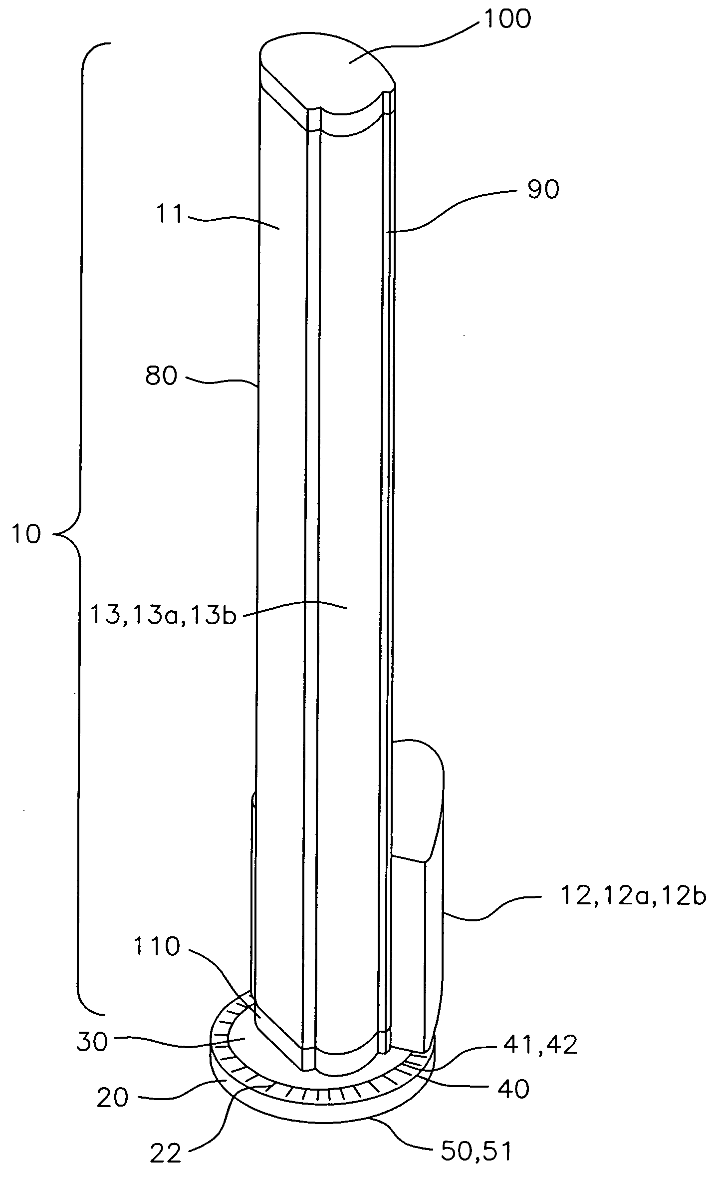
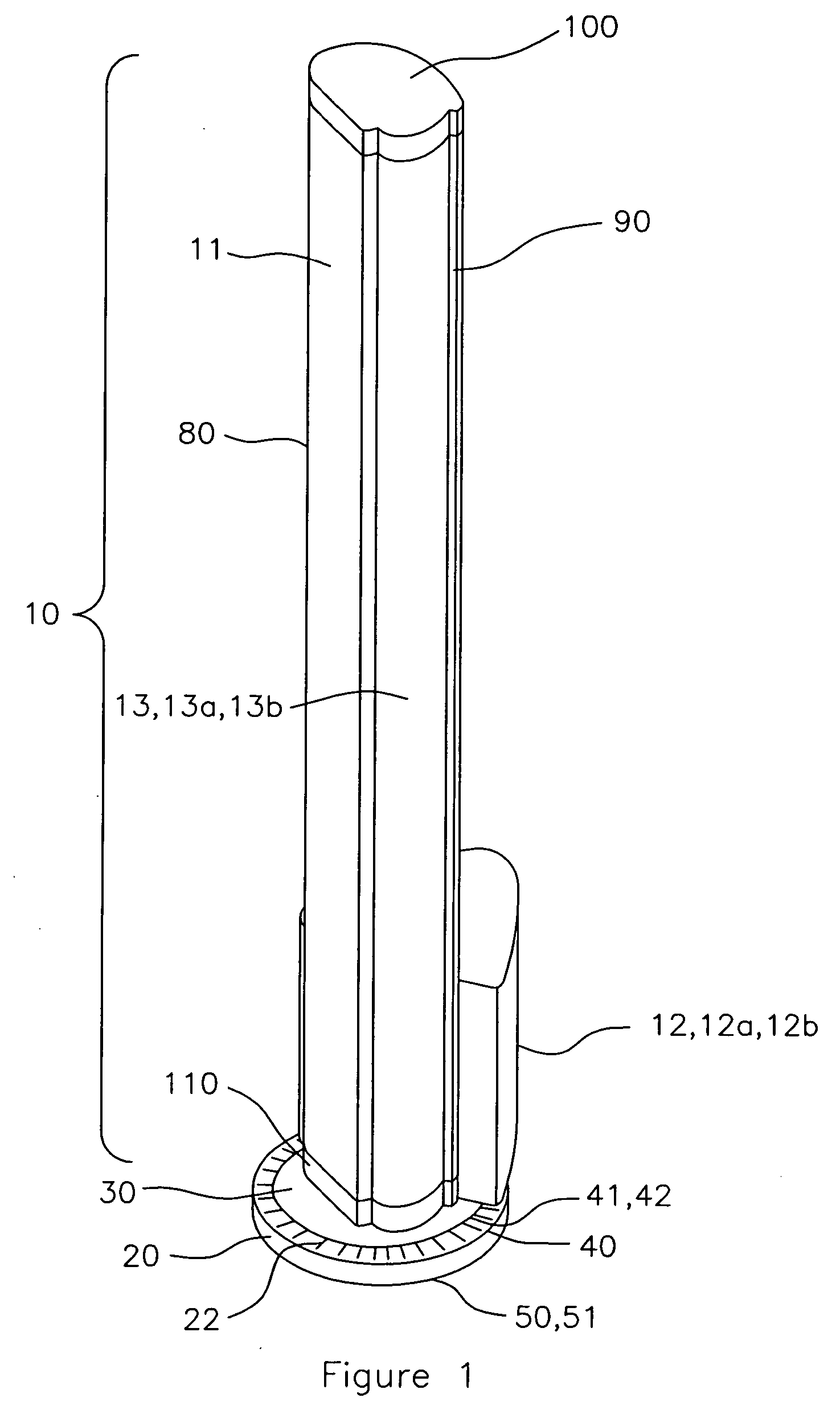
[0010]FIG. 1 is a perspective view of a surround sound system, in accordance with the present invention.

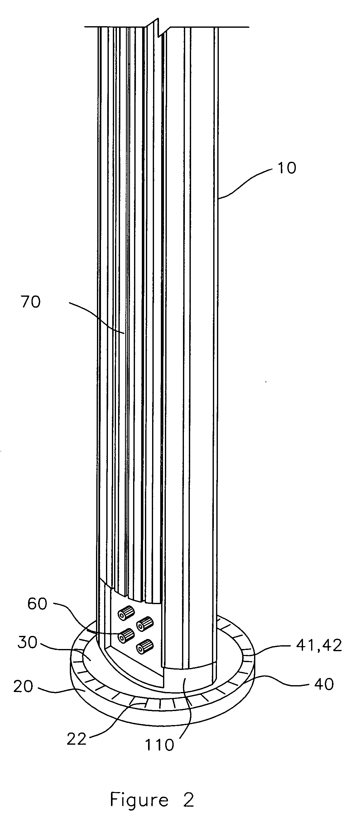
[0011]FIG. 2 is a cut-away rear perspective view of a surround sound system, in accordance with the present invention.

[0012]FIG. 3 is a cross-sectional view of a tower, in accordance with the present invention.

[0013]FIG. 4 is a front elevation view of a speaker, in accordance with the present invention.

[0014]FIG. 5 is a front elevation view of a tower, in accordance with the present invention.

[0015]FIG. 6 is a side view of a tower, at cross-sections A-A and B-B, in accordance with the present invention.

[0016]FIG. 7 is a rear view of a tower, in accordance with the pr...


PUM


Abstract

A surround sound system and method involving a surround sound tower (10) having planar speakers (11b); a base plate (20); and a structure for positioning (30) the surround sound tower on the base plate (20), the surround sound tower (10) being mounted on, and normal to, the positioning structure (30) for customizing sound direction and constructive interference patterns by interactively positioning the sound tower (10) and by modular usage of both sub-woofers (12a) and tweeters (13a), economizing floor space, especially in a home theater environment, the positioning structure (30) having a structure for indicating an angular rotation (40) of the surround sound tower (10) relative to the base plate (20) and a structure for facilitating rotation (50) of the angular rotation indicating structure (40).

Description

CROSS-REFERENCE TO RELATED APPLICATION(S) [0001] The present continuation-in-part application is related to, and claims priority from, U.S. Ser. No. 10 / 655,095, entitled “Surround Sound Positioning Tower System and Method” and filed Sep. 3, 2003.TECHNICAL FIELD [0002] The present invention relates to surround sound systems and methods. More particularly, the present invention relates to surround sound tower systems and methods. Even more particularly, the present invention relates to surround sound positioning tower systems and methods. BACKGROUND ART [0003] Installing a home theater system which recreates the acoustic experience of any given soundtrack is vital to meeting the electronic consumer's expectations. Current art home theater surround sound systems typically involve compact disc / digital video disc (CD / DVD) players or changers, audio / visual (A / V) receivers, tuners, equalizers, headphones, satellite speakers, center channel speakers, woofers or subwoofers disposed in a fixe...

Claims


Application Information

Patent Timeline
IPC IPC(8): H04R1/02H04R5/02H04R9/06H04S3/00H04S7/00
CPCH04R5/02H04R1/026
Inventor LEE, NOELMARTIN, DEMIAN
Owner MONSTER
Why Eureka
Try Eureka