Semi-submersible offshore vessel

a technology of submerged vessels and offshore vessels, applied in floating buildings, bulkheads/piles, artificial islands, etc., can solve problems such as metal fatigue sensitiveness, and achieve the effect of high exciting forces and low exciting forces

Active Publication Date: 2005-03-17
GVA GONSULTANTS
View PDF8 Cites 29 Cited by
  • Summary
  • Abstract
  • Description
  • Claims
  • Application Information

AI Technical Summary

Benefits of technology

[0012] This is achieved by rendering one end of the vessel (below referred to as the second end) rotationally “stiff” by providing the support columns in a second column pair with relatively large water-plane areas, in combination with a relatively slender conFIG.uration of a corresponding second transversal pontoon section, which results in low exciting forces in the vertical direction at the second end compared to the first end of the vessel. The first end, on the other hand, is rendered rotationally “Weak” by providing the support columns in the first column pair with relatively small water-plane areas, in combination with a relatively wide conFIG.uration of the first transversal pontoon section—which results in higher exciting forces in the vertical direction at the first end.

Problems solved by technology

Production riser pipes are often made of steel, so called Steel Catenary Risers (SCR), and are sensitive to metal fatigue as the pipes are subjected to forces and motions caused primarily by the wave excited vertical motions of the semi-submersible offshore vessel.

Method used


Image

  • Semi-submersible offshore vessel
  • Semi-submersible offshore vessel
  • Semi-submersible offshore vessel

Examples


Embodiment Construction

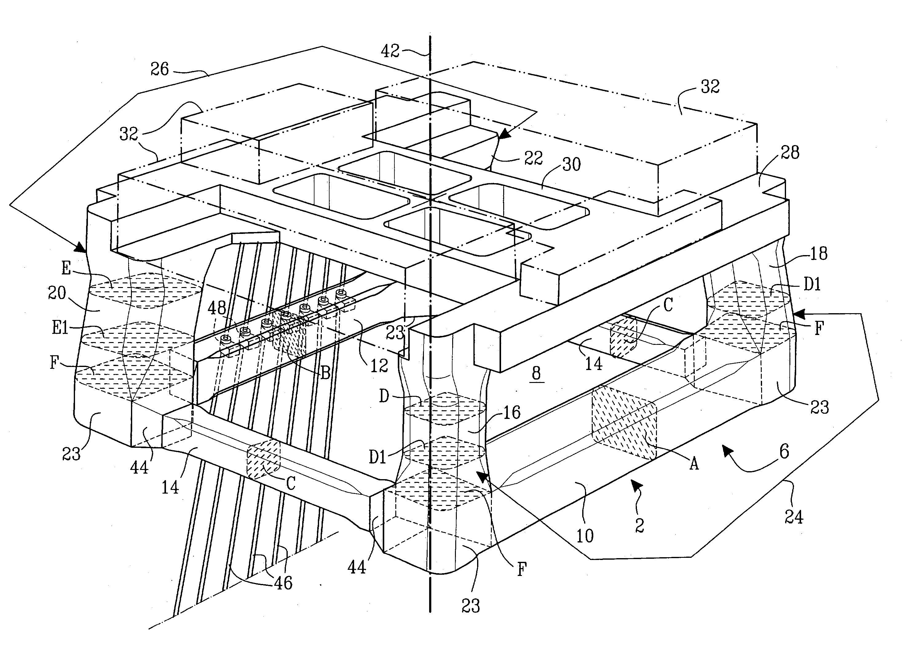
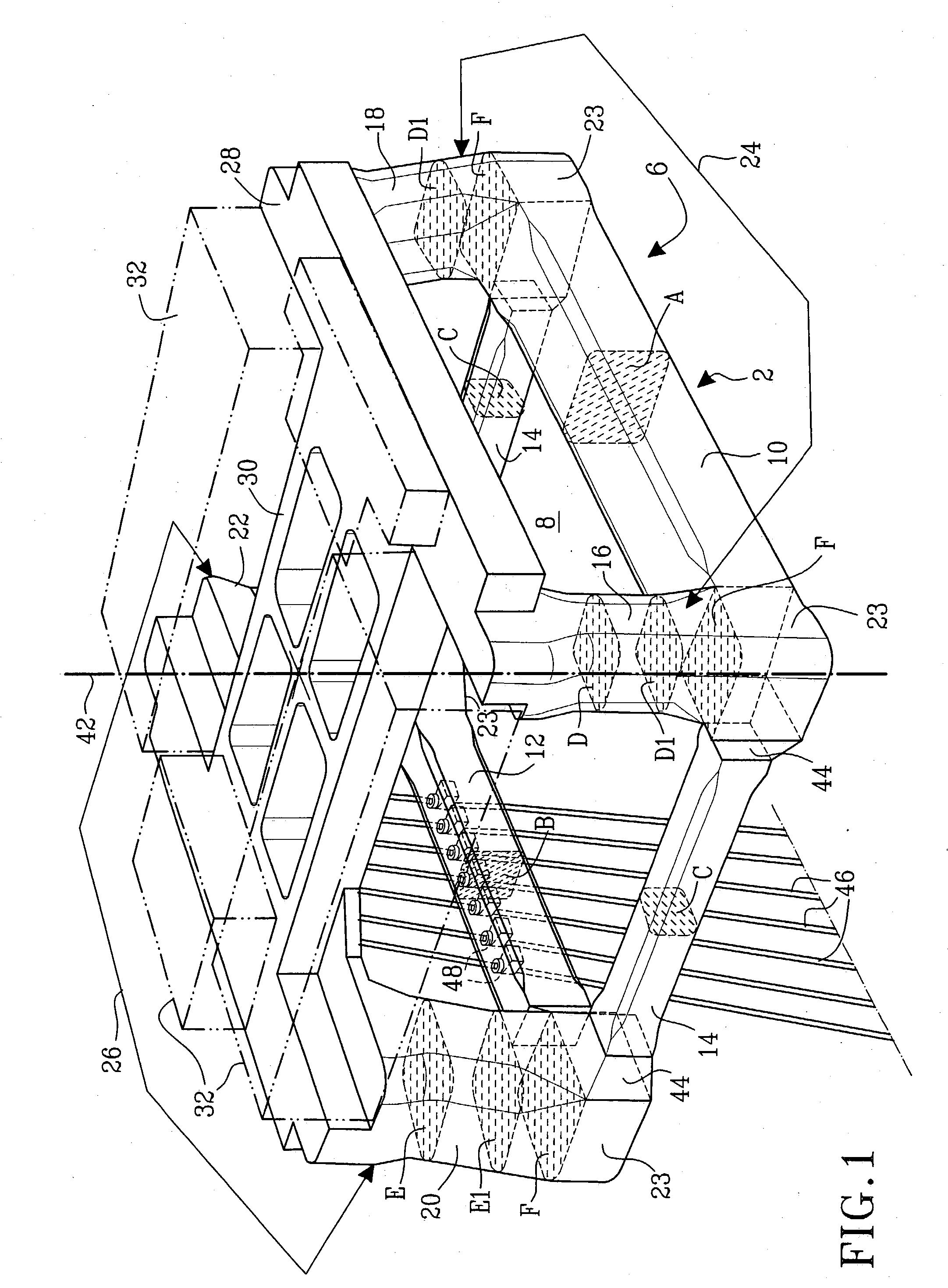
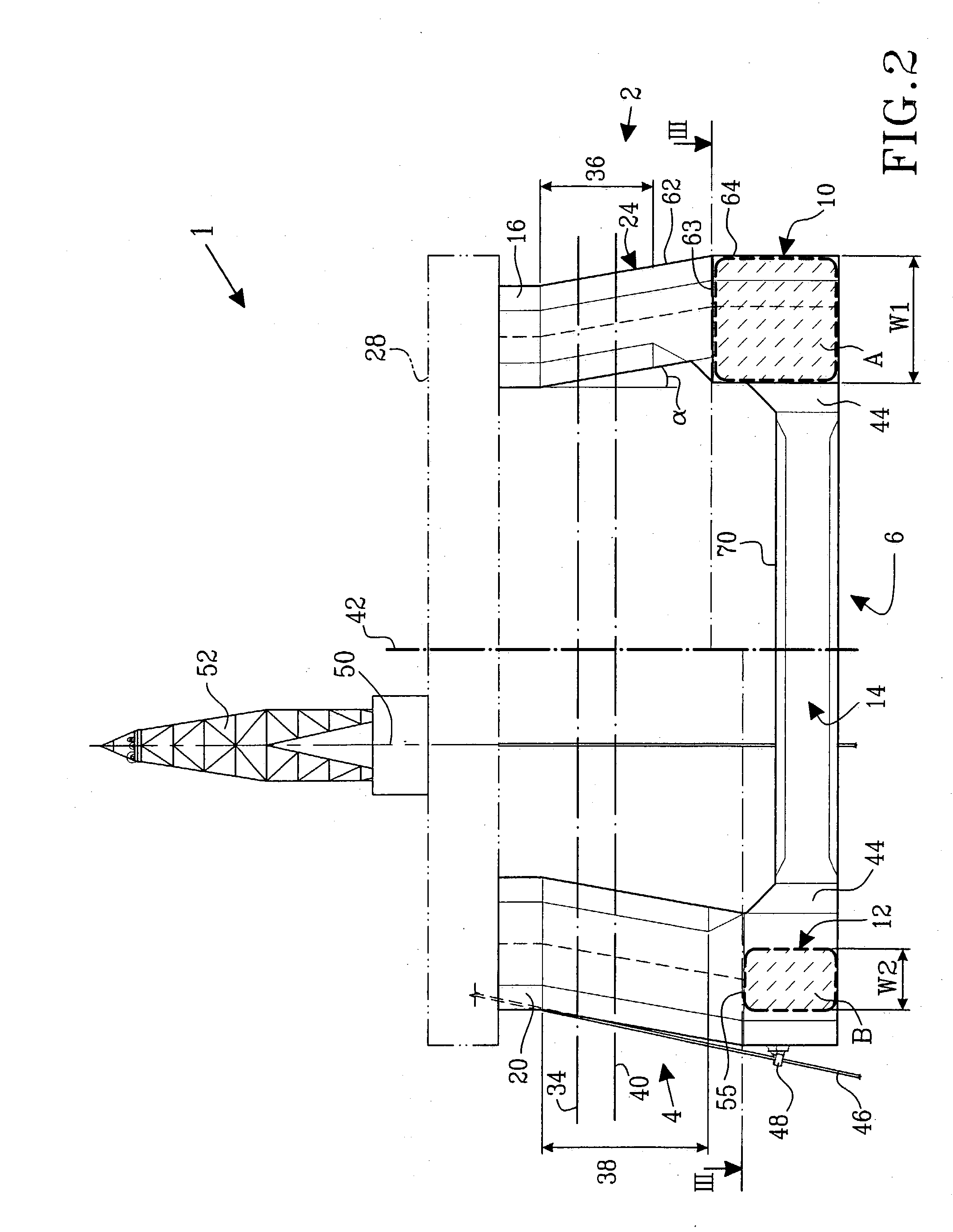
[0044] The present invention will hereinafter be described with reference to the accompanying drawings. In FIG. 1, reference numeral 1 denotes a semi-submersible offshore vessel according to a first exemplary embodiment of the invention. The offshore vessel 1 exhibits a first end 2 or example constituting the forward end of the vessel 1, and a second end 4, for example constituting the aft end of the vessel 1- or vice versa depending on definition preferences due to some embodiments being essentially of a square configuration.

[0045] The offshore vessel 1 includes a substantially rectangular ring-pontoon 6. The term “ring-pontoon” is here defined as a closed pontoon structure, which encloses a central opening 8. The ring-pontoon 6 includes a first transverse pontoon section 10 located at the first end 2 of the vessel 1, and a second transverse pontoon section 12 located at the second end 4 of the vessel 1. The second transverse pontoon section 12 is parallel to the first transverse ...


PUM


Abstract

A semi-submersible offshore vessel (1) exhibiting a first end (2), for example constituting the forward end of the vessel, and a second end (4), for example constituting the aft end of the vessel (1), or vice versa, wherein the vessel (1) includes a substantially rectangular ring-pontoon (6) including a first transverse pontoon section (10) located at the first end (2) of the vessel (1); a second transverse pontoon section (12) located at the second end (4) of the vessel (1), the second transverse pontoon section (12) being parallel to the first transverse pontoon section (10), the ring-pontoon (6) further including two mutually parallel longitudinal pontoon sections (14) extending between the first (2) and the second end (4) of the vessel (1); at least four support columns (16, 18, 20, 22) extending upwardly from respective edge-portions (23) of said ring-pontoon (2), the support columns (16, 18, 20, 22) being arranged in a first column pair (24) located at the first end (2) of the vessel (1) and a second column pair (26) located at the second end (4) of the vessel (1); and an upper deck structure (28) positioned upon the support columns (16, 18, 20, 22). The first transverse pontoon section (10) may also include a vertical mean cross-section area (A) which exceeds the corresponding vertical mean cross-section area (B) of the second transverse pontoon section (12), and the support columns (20, 22) in the second column pair (26) each has a water-plane area (E) which exceeds the water-plane area (D) of each of the support columns (16, 18) in the first column pair (24).

Description

CROSS-REFERENCES TO RELATED APPLICATIONS [0001] This nonprovisional application claims priority under 35 U.S.C. § 119(a) on Patent Application No. 0301646-6 filed in Sweden on Jun. 4, 2003, the entirety of which is herein incorporated by reference. BACKGROUND OF THE INVENTION [0002] 1. Field of the Invention [0003] The present invention relates to a semi-submersible offshore vessel of a type used for deep water offshore operations such as oil and gas exploration, drilling and production. The invention introduces a novel way of minimizing motions, and primarily the vertical motions of the vessel, in order to reduce metal fatigue in—for example—riser pipe structures. The vessel exhibits a substantially rectangular ring-pontoon, at least four support columns and an upper deck structure positioned upon said support columns. The offshore vessel may for example be provided with hydrocarbon processing equipment and / or accommodation quarters. [0004] 2. Description of the Background Art [000...

Claims


Application Information

Patent Timeline
Patent Type & Authority Applications(United States)
IPC IPC(8): B63B1/10B63B35/44
CPCB63B1/107B63B2001/128B63B35/4413
Inventor MARTENSSON, NILSERNBY, THOMASLIU, YUNGANG
Owner GVA GONSULTANTS
Why Eureka
Try Eureka