Constant velocity universal joint

a constant velocity, universal joint technology, applied in the direction of yielding couplings, couplings, rotary machine parts, etc., can solve the problems of reducing the design freedom of the underbody of the vehicle, affecting the nvh characteristics, and increasing the induced thrust, so as to achieve favorable nvh characteristics

Active Publication Date: 2005-03-17
NTN CORP
View PDF2 Cites 12 Cited by
  • Summary
  • Abstract
  • Description
  • Claims
  • Application Information

AI Technical Summary

Benefits of technology

[0016] According to the present invention, the outer peripheral surface of the roller has a surface roughness of 0.35 Ra or less, whereby the wear occurring in the roller guide surface of the outer joint member after expiration of the endurance life can be suppressed, hence the induced thrust and sliding resistance caused by such wear can be stabilized at a low level, and favorable NVH characteristics can be obtained.

Problems solved by technology

Since the roller and the roller guide surface are positioned obliquely to each other along with the inclination of the trunnion when rotational torque is transmitted with a working angle being formed between the outer joint member and the tripod member, the roller will slip with respect to the roller guide surface to inhibit the smooth rolling of the roller, posing a problem of increasing the induced thrust.
In the meantime, the induced thrust and the sliding resistance as mentioned above are responsible for vibration or noise of a vehicle body, affecting the NVH characteristics of the vehicle, and reduce the design freedom of the underbody of a vehicle.
Therefore, when the joint is employed for a drive shaft of a vehicle, restriction is imposed on the design such that the working angle cannot be made large.
In order to increase the degree of design freedom of the underbody of a vehicle, there has been problem to stabilize the induced thrust or the sliding resistance at a low level.
On the other hand, in this type of constant velocity universal joint, some wear occurs in the roller guide surface of the outer joint member after its endurance life has expired.
In a constant velocity universal joint exhibiting low vibration performance, particularly, there has been a problem that, if wear occurs on the roller guide surface of the outer joint member after expiration of the endurance life, it becomes difficult to reduce the induced thrust due to such wear, and thus the NVH characteristics are deteriorated remarkably.

Method used


Image

  • Constant velocity universal joint
  • Constant velocity universal joint
  • Constant velocity universal joint

Examples


Embodiment Construction

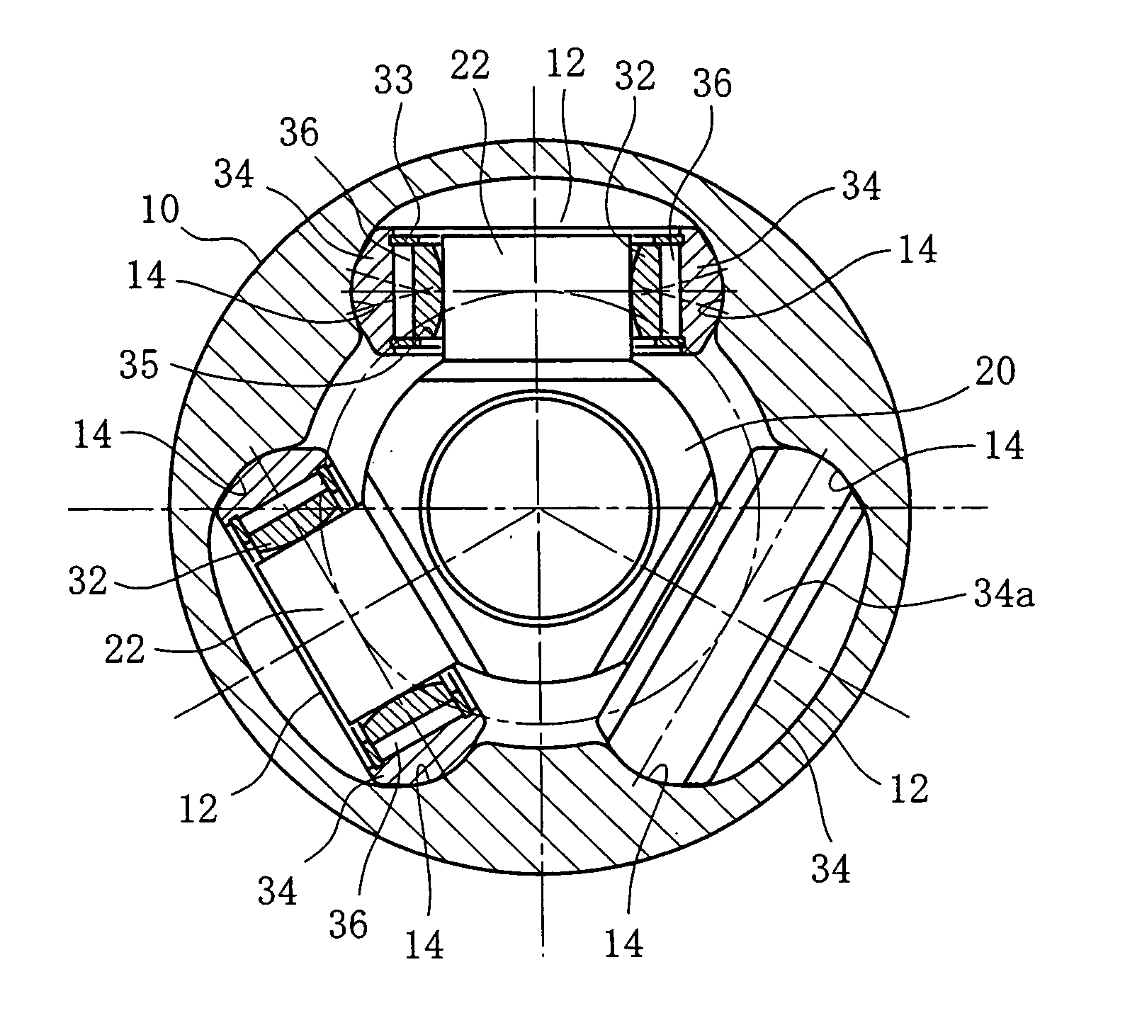
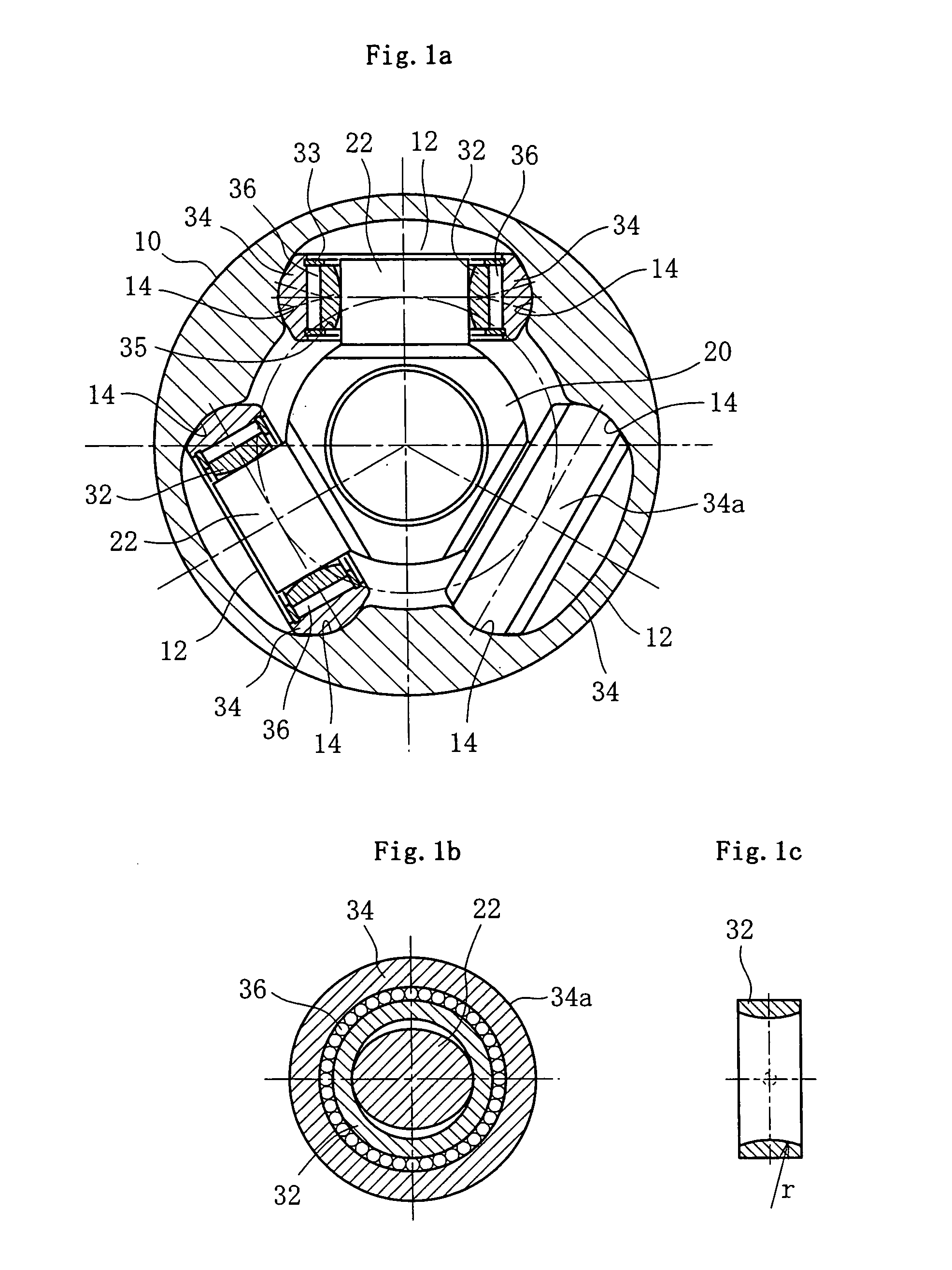
[0021]FIG. 1a is a cross sectional view of a joint, FIG. 1b is a section vertical to the trunnion, and FIG. 1c is a section of a ring.

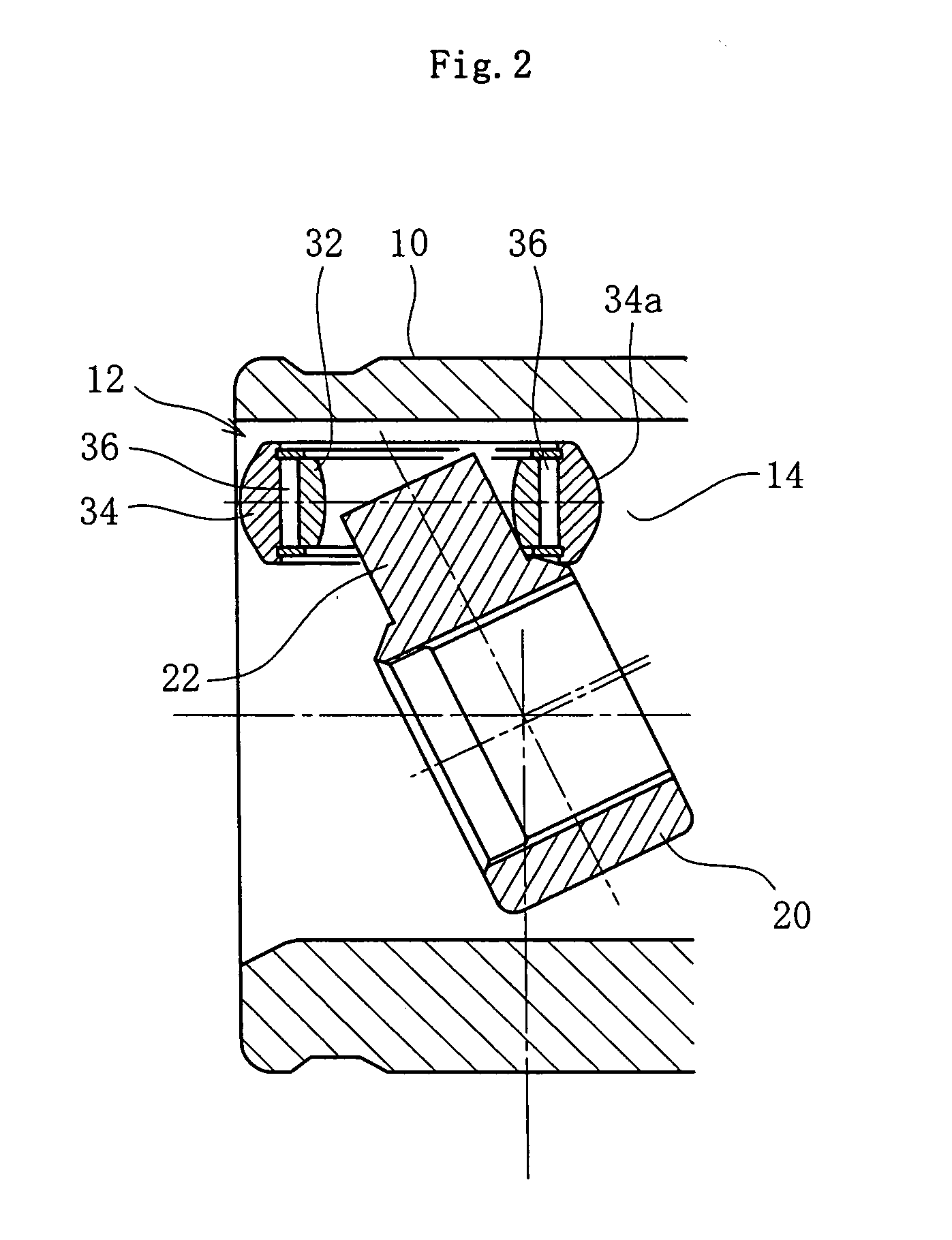
[0022] A tripod type constant velocity universal joint according to this embodiment is constituted chiefly by an outer joint member 10 and a tripod member 20 as shown in FIG. 1. The outer joint member 10 is connected with one of two shafts to be connected together, namely a driving shaft and a driven shaft, and the tripod member 20 is connected with the other shaft, whereby, even when a working angle is formed between the shafts, rotational torque can be transmitted at a constant velocity and, moreover, relative displacement in the axial direction is allowed.

[0023] The outer joint member 10 has a substantially cylindrical cup shape, one end of which is open and the other end of which is closed. One of the shafts (not shown) is provided integrally at the other end, and three track grooves 12 extending axially are formed in the inner circumference at ...


PUM


Abstract

An object is to stabilize the induced thrust and the sliding resistance at a low level after expiration of the endurance life and exhibit favorable NVH characteristics. A constant velocity universal joint comprises: an outer joint member having three track grooves formed to extend axially in an inner circumference portion thereof, and having a roller guide surface formed to extend axially on each side of the respective track grooves; a tripod member having three trunnions protruding in the radial direction; and a roller mechanism mounted in each of the trunnions of the tripod member. The roller mechanism is capable of swinging and oscillating freely with respect to the trunnions, and has a roller that is guided along the roller guide surface in the direction parallel to the axis line of the outer joint member. In the constant velocity universal joint, the outer peripheral surface of the roller has a surface roughness of 0.35 Ra or less.

Description

BACKGROUND ART [0001] The present invention relates to a sliding type tripod constant velocity universal joint applicable to a power transmission unit in vehicles, aircrafts, vessels, and various industrial equipment. Generally, a constant velocity universal joint is a type of universal joints for connecting two shafts, a driving shaft and a driven shaft, and capable of transmitting rotational force at a constant velocity even if there is an angle between the two shafts. A sliding joint is a joint which allows relative displacement of the two shafts in the axial direction by the plunging of the joint. A tripod type joint is designed to transmit torque between two shafts by coupling a tripod member having three trunnions protruding in the radial direction to one of the shafts, while coupling an outer joint member with a hollow cylindrical shape provided with three track grooves extending in the axial direction to the other shaft, such that the trunnions of the tripod member are recei...

Claims


Application Information

Patent Timeline
Patent Type & Authority Applications(United States)
IPC IPC(8): F16D3/205
CPCY10S464/905F16D3/2055F16D2003/2026
Inventor GOTO, TATSUHIROMURAKAMI, HIROSHIMIYATA, MASAHIDETOMIYAMA, MIKIO
Owner NTN CORP
Why Eureka
Try Eureka