
Combination bat for baseball

Inactive Publication Date: 2005-03-17
CHANG JUNG SHIH
View PDF18 Cites 18 Cited by
  • Summary
  • Abstract
  • Description
  • Claims
  • Application Information

AI Technical Summary

Benefits of technology

[0007] It is one object of the present invention to provide a combination bat, which has a light weight, good equilibrium, and high structural strength for a good performance.
[0008] It is another object of the present invention to provide a combination bat, which produces less shock when hitting the ball.
[0010] It is still another object of the present invention to provide a combination bat, which has the surface well protected against damage.
[0011] To achieve these and other objects of the present invention, the combination bat comprises a wood body having a handle and a barrel extending from one end of the handle. At least one tubular core made of fiber reinforced plastic materials is axially received inside the wood body. The combination bat may further comprise at least one shock-absorbing member installed in the tubular core(s) to lessen shocks when hitting the ball or one weighting member installed in the tubular core to adjust the center of gravity of the bat. The periphery of the barrel of the combination bat may be covered with a reinforced layer made of FRP materials to improve the surface strength.

Problems solved by technology

However, wood bats have numerous drawbacks, such as heavy weight and bad equilibrium.
Due to the aforesaid drawbacks, it requires much effort to hit the ball with the bat, and the bat cannot drive the ball to a long distance.
Further, a wood bat is weak and easy to break, and produces severe shocks when hitting the ball.
However, an aluminum bat produces shocks, noises and dents at barrel when hitting the ball.
However, the problem is that the FRP bat is so expensive that can not be popular used.

Method used


Image

  • Combination bat for baseball
  • Combination bat for baseball
  • Combination bat for baseball

Examples


first embodiment

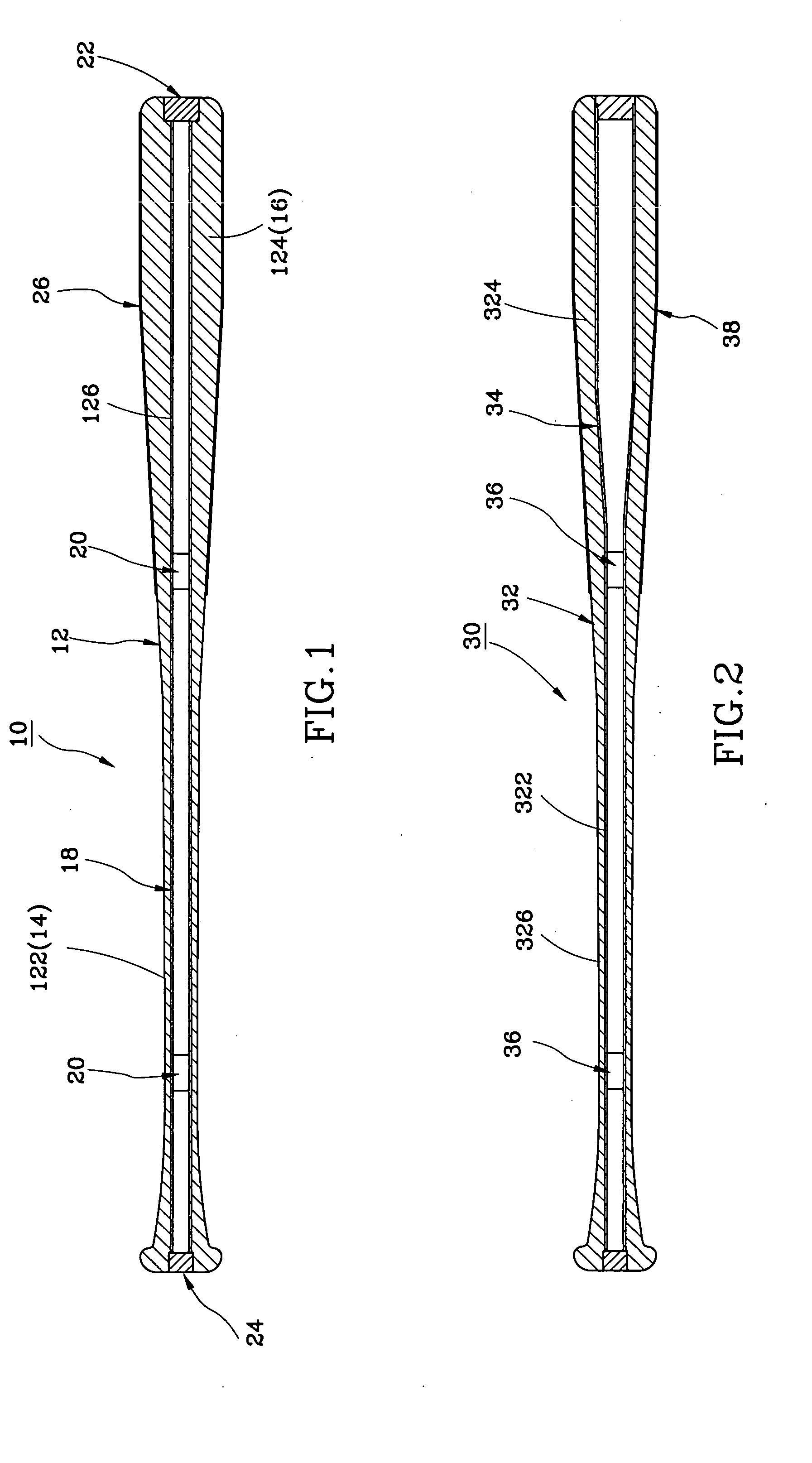
[0021] Referring to FIG. 1, a combination bat, referenced by 10, in accordance with the present invention is shown comprising a wood body 12, a core 18, two shock-absorbing member 20, a front end plug 22, a rear end plug 24, and a cover layer 26.

[0022] The wood body 12 having the shape of a conventional bat for baseball includes a rear part 122 forming a handle 14, a front part124 forming a barrel 16. The body 12 has an axial hole 126 axially extended through the two ends thereof.

[0023] The core 18 is a tubular member made of fiber reinforced plastic materials, for example, carbon fiber reinforced epoxy resin, having an outer diameter fitting the diameter of the axial hole 126 to be tightly received in the axial hole 126.

[0024] The two shock-absorbing members 20 are cylindrical members respectively made of shock-absorbing materials such as foamed plastic, cloth or cork and tightly inserted into the inside of the core 18 at selected locations. The shock-absorbing members 20 can be ...

second embodiment

[0026] In production, the bat can be variously embodied. FIG. 2 shows a combination bat 30 constructed according to the present invention. According to this embodiment, the wood body 32 has an axial hole 322 axially extended through the two ends. The diameter of the axial hole 322 is changed subject to the outer diameter of the body 32, i.e., the diameter of the front portion of the axial hole 322 in the barrel 324 is relatively larger than the diameter of the rear portion of the axial hole 322 in the handle 326, and the diameter of the axial hole 322 in the middle area between the handle 326 and the barrel 324 is gradually increased in direction from the handle 326 toward the barrel 324.

[0027] An integrated tubular core 34 is received in the axial hole 322. Two shock-absorbing members 36 (or two weights, or a weight at the front side and a shock-absorbing member at the rear side, or other combination) are inserted into the inside of the core 34. A cover layer 38 is made of fiber re...

third embodiment

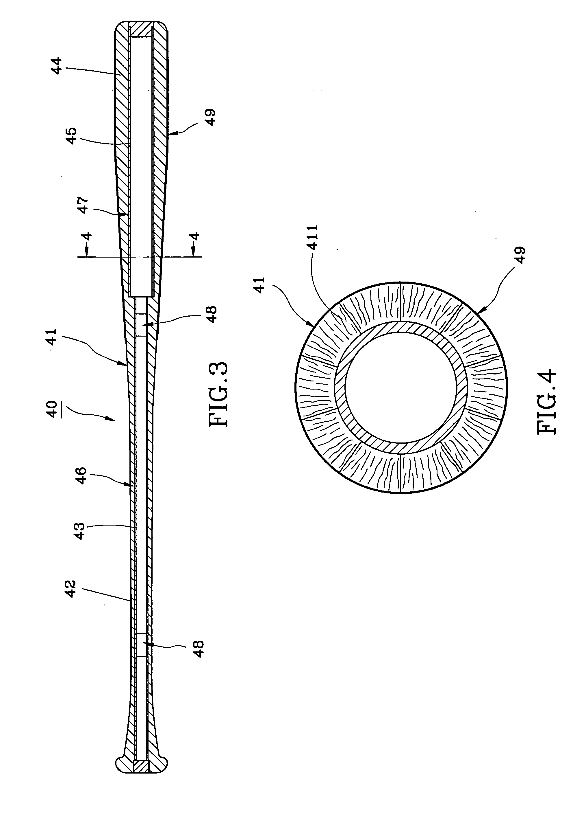
[0028]FIGS. 3 and 4 shows a combination bat 40 constructed according to the present invention. According to this embodiment, the whole wood body 41 is made of same material, having a first axial hole 43 with a first diameter in the handle 42 and a second axial hole 45 with a second diameter in the barrel 44. The second diameter of the second axial hole 45 is relatively larger than the first diameter of the first axial hole 43. A first tubular core 46 and a second tubular core 47 are respectively received in the first axial hole 43 and the second axial hole 45.

[0029] The body 41 can be formed of a plurality of transversely arched wood blocks 411 abutted against and adhered to one another. According to this embodiment, the body 41 is formed of ten wood blocks 411 symmetrically arranged together (as shown in FIG. 4). The number of the wood blocks 411, of course, can be 2, 4, 8, etc. The wood blocks 411 may be not symmetrical. The grains of each wood block 411 substantially extend in th...


PUM


Abstract

A combination bat includes a wood body and a tubular core. The wood body has a handle, a barrel extending from one end of the handle, and an axial hole. The tubular core is made of fiber reinforced plastic materials and axially received inside the axial hole of the wood body. A shock-absorbing member is inserted inside the tubular core.

Description

BACKGROUND OF THE INVENTION [0001] 1. Field of the Invention [0002] The present invention relates to bats for baseball and, more particularly, to a combination bat, which comprises a hollow wood body and at least one tubular core made of fiber reinforced plastic materials and axially fitted into the inside of the hollow wood bat body. [0003] 2. Description of the Related Art [0004] Wood bats are most popularly used because they are the cheapest ones. However, wood bats have numerous drawbacks, such as heavy weight and bad equilibrium. In other words, the center of gravity is biased to the side of the barrel end. The center of gravity of a wood bat is at about 11 inches from the barrel end, however the ideal center of gravity should be at the area within 14˜14.5 inches from the barrel end. Due to the aforesaid drawbacks, it requires much effort to hit the ball with the bat, and the bat cannot drive the ball to a long distance. Further, a wood bat is weak and easy to break, and produc...

Claims


Application Information

Patent Timeline
IPC IPC(8): A63B59/52A63B59/54A63B59/56A63B60/02A63B60/54A63B102/18
CPCA63B59/0088A63B2209/02A63B59/06A63B59/0092A63B59/50A63B59/52A63B59/54A63B60/50A63B60/54A63B2102/18
Inventor CHANG, JUNG-SHIH
Owner CHANG JUNG SHIH
Learn More