Remotely activated mitral annuloplasty system and methods

a mitral annuloplasty and remote activation technology, applied in the field of intravascular prosthesis, can solve the problems of congestive heart failure, pulmonary venous pressure and cardiac output reduction, and the vicious cycle of progressive enlargement and worsening of mitral regurgitation

a mitral annuloplasty and remote activation technology, applied in the field of intravascular prosthesis, can solve the problems of congestive heart failure, pulmonary venous pressure and cardiac output reduction, and the vicious cycle of progressive enlargement and worsening of mitral regurgitation

US20050060030A1Inactive Publication Date: 2005-03-17EDWARDS LIFESCIENCES AG

Image

  • Remotely activated mitral annuloplasty system and methods
  • Remotely activated mitral annuloplasty system and methods
  • Remotely activated mitral annuloplasty system and methods

Examples


Embodiment Construction

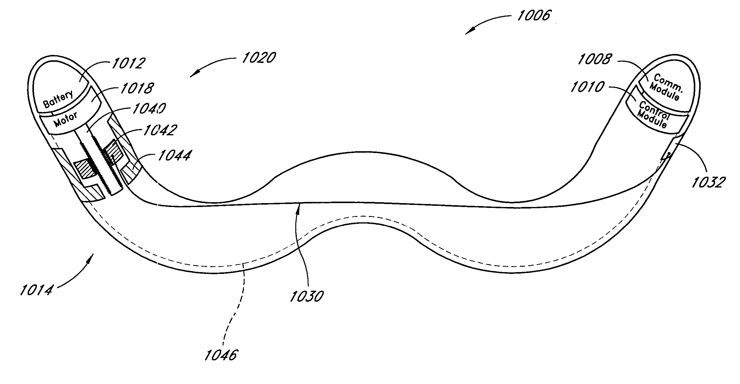
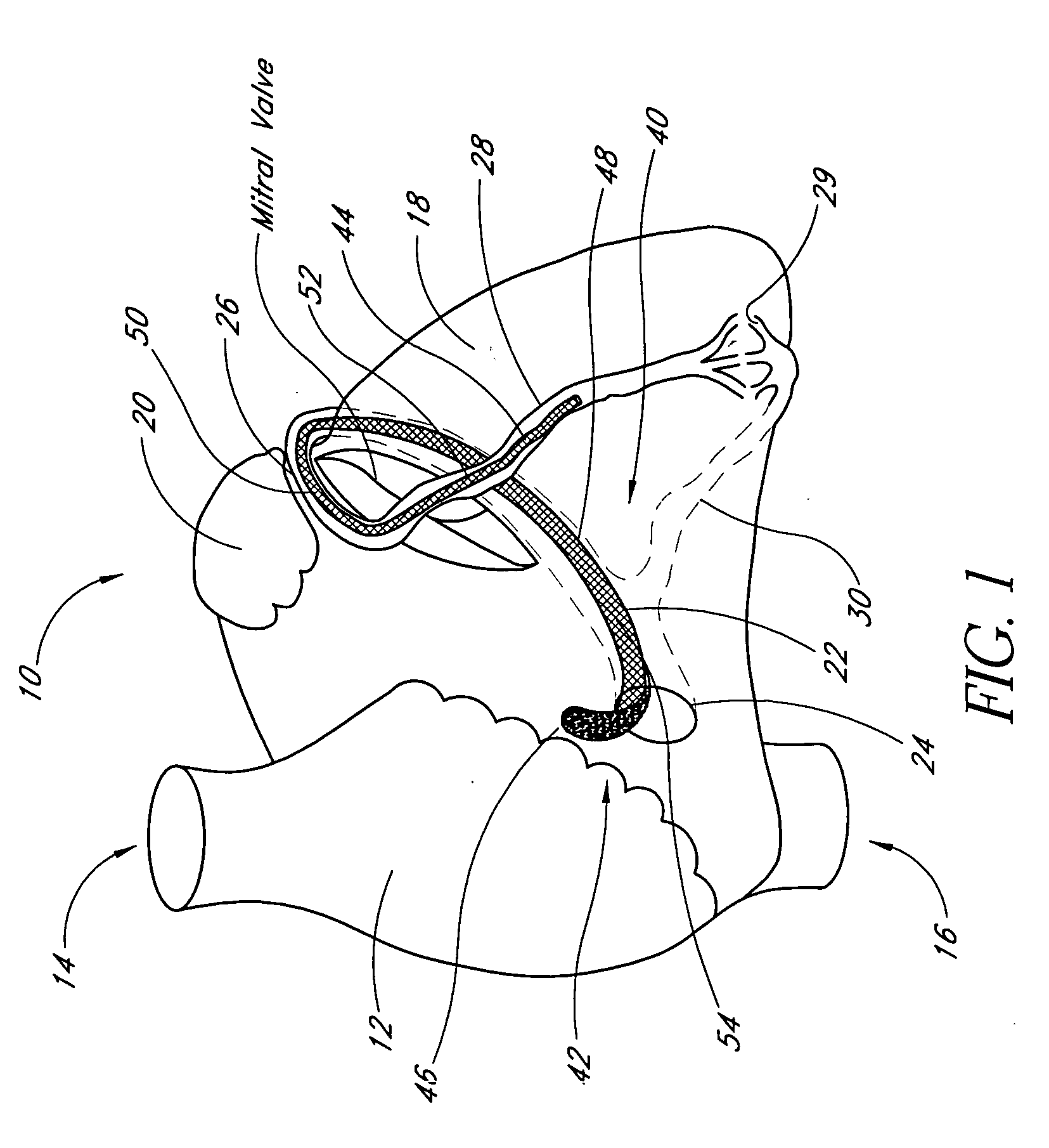
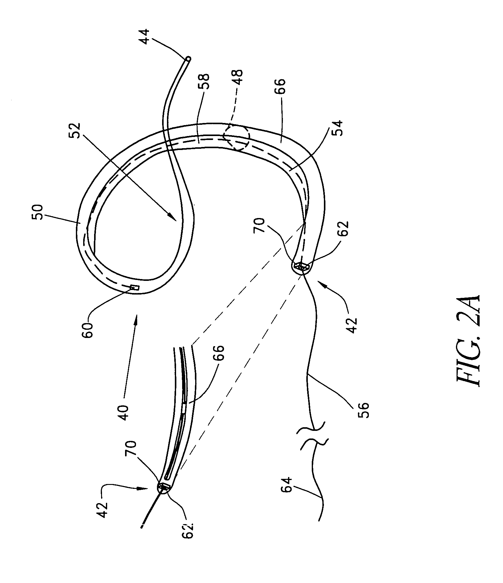
[0111] Preferred embodiments of the present invention include a method and apparatus for performing mitral annuloplasty and remodeling of the left ventricle using a device that may be introduced percutaneously, and placed within the coronary venous system of the heart. The device exerts compressive force on the mitral annulus and left ventricle, reducing the severity of mitral regurgitation and the size of the left ventricular cavity. The device thus enables reduction of the mitral annulus and constraint of the diastolic expansion of the left ventricle yet without the morbidity and other risks associated with open chest surgery. Additional details are disclosed in the parent application Ser. No. 10 / 066,302, filed on Jan. 30, 2002, the disclosure of which is incorporated in its entirety herein by reference.

[0112] The present inventors have determined that the coronary sinus and veins provide an ideal conduit for the positioning of an intravascular prosthesis, or implant, for remodel...


PUM


Abstract

Disclosed are implants and methods for remote remodeling of a mitral valve annulus. The implant comprises a body transformable from a flexible configuration for navigation to a treatment site, to a remodeling configuration for, in one application, applying pressure to the posterior leaflet of the mitral valve. On board electronics allow post deployment adjustment of the implant.

Description

RELATED APPLICATIONS [0001] This application is a continuation-in-part of U.S. application Ser. No. 10 / 634,655, filed Aug. 5, 2003, which claims priority from U.S. Provisional No. 60 / 429,281, filed Nov. 25, 2002, and which is a continuation-in-part of U.S. application Ser. No. 10 / 066,302, filed Jan. 30, 2002, which claims priority from U.S. Provisional No. 60 / 265,995, filed Feb. 1, 2001, and which is a continuation-in-part of U.S. application Ser. No. 09 / 774,869, filed Jan. 30, 2001, now U.S. Pat. No. 6,537,314, which is a continuation-in-part of U.S. application Ser. No. 09 / 494,233, filed Jan. 30, 2000, now U.S. Pat. No. 6,402,781 all of which are incorporated by reference herein. This application also claims priority from U.S. Provisional No. 60 / 488,334, filed Jul. 18, 2003, which is incorporated by reference herein.BACKGROUND OF THE INVENTION [0002] 1. Field of the Invention [0003] The present invention relates to intravascular prostheses for remodeling an extravascular anatomica...

Claims


Application Information

Patent Timeline
17 Mar 2005
Publication
US20050060030A1
IPC
A61B5/00; A61F2/02; A61F2/24
CPC
A61B5/6882; A61B2560/0219; A61F2250/0001; A61F2/2466; A61F2/2451
Inventors
LASHINSKI, RANDALL T.; VON HOFFMANN, GERARD