Methods and devices for determining a correction value for a measured segment time

a technology of segment time and correction value, which is applied in the direction of instruments, electrical control, force/torque/work measurement apparatus, etc., can solve the problems of inability to adapt to small rotational speed gradients, mechanical defects or inaccuracy of markings or tachometer disks, and inability to detect misfires more accurately, so as to increase customer satisfaction and facilitate compliance. , the effect of detecting misfires

Active Publication Date: 2005-03-24
VITESCO TECH GMBH
View PDF4 Cites 6 Cited by
  • Summary
  • Abstract
  • Description
  • Claims
  • Application Information

AI Technical Summary

Benefits of technology

that is, the adaption value determined corresponds precisely to the predetermined error F, irrespective of any rotational-speed gradients present. This is particularly advantageous since the adaption values in some internal combustion engines are subject to rotational-speed-

Problems solved by technology

In practice, however, the markings or the tachometer disk can have mechanical defects or inaccuracies, for example angular errors of the segments or marking teeth of the tachometer disk, a disk eccentricity or variances in the form of the teeth.
Such defects or inaccuracies lead to the result of the angular-velocity measurements b

Method used


Image

  • Methods and devices for determining a correction value for a measured segment time
  • Methods and devices for determining a correction value for a measured segment time
  • Methods and devices for determining a correction value for a measured segment time

Examples


first embodiment

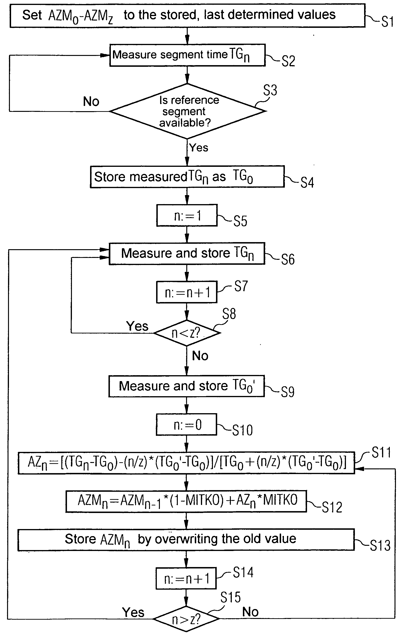
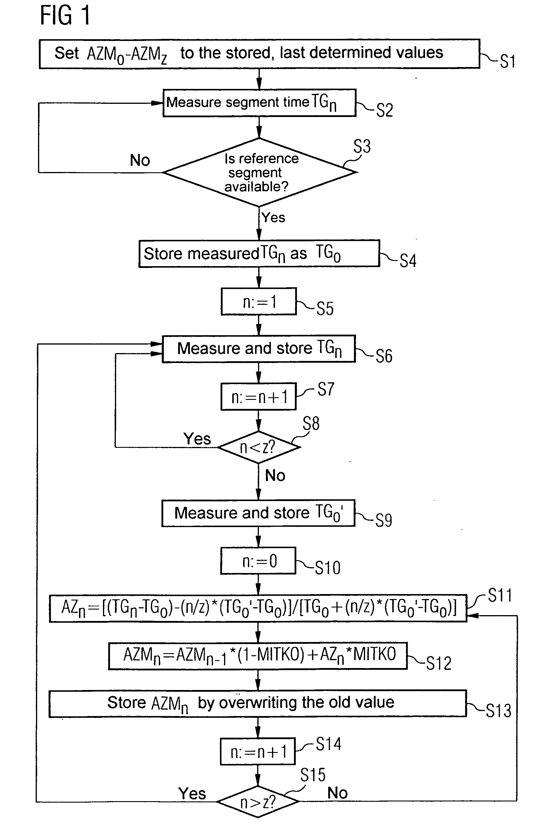
FIG. 1 shows the inventive method, the embodiment shown in FIG. 1 being provided for determining correction values for individual cylinders. The method shown begins with step S1, in which the averaged correction values AZM0 to AZMn are set to the stored, last determined values, so that the averaged correction values AZM0 to AZMn have the values which applied during the last engine operation. In step S2 of the method, the segment time TGn of the current segment n is measured. A check is then performed in step S3 of the method as to whether the measured segment time was the time of the reference segment. A random segment can be chosen as a reference segment, advantageously the first in the ignition sequence of the cylinders. This reference segment is defined or assumed to be free from defects. If it was established in step S3 that the reference segment is not available, then the flow branches back to step S2, and the next segment time TGn is measured. As soon as it is established in s...

second embodiment

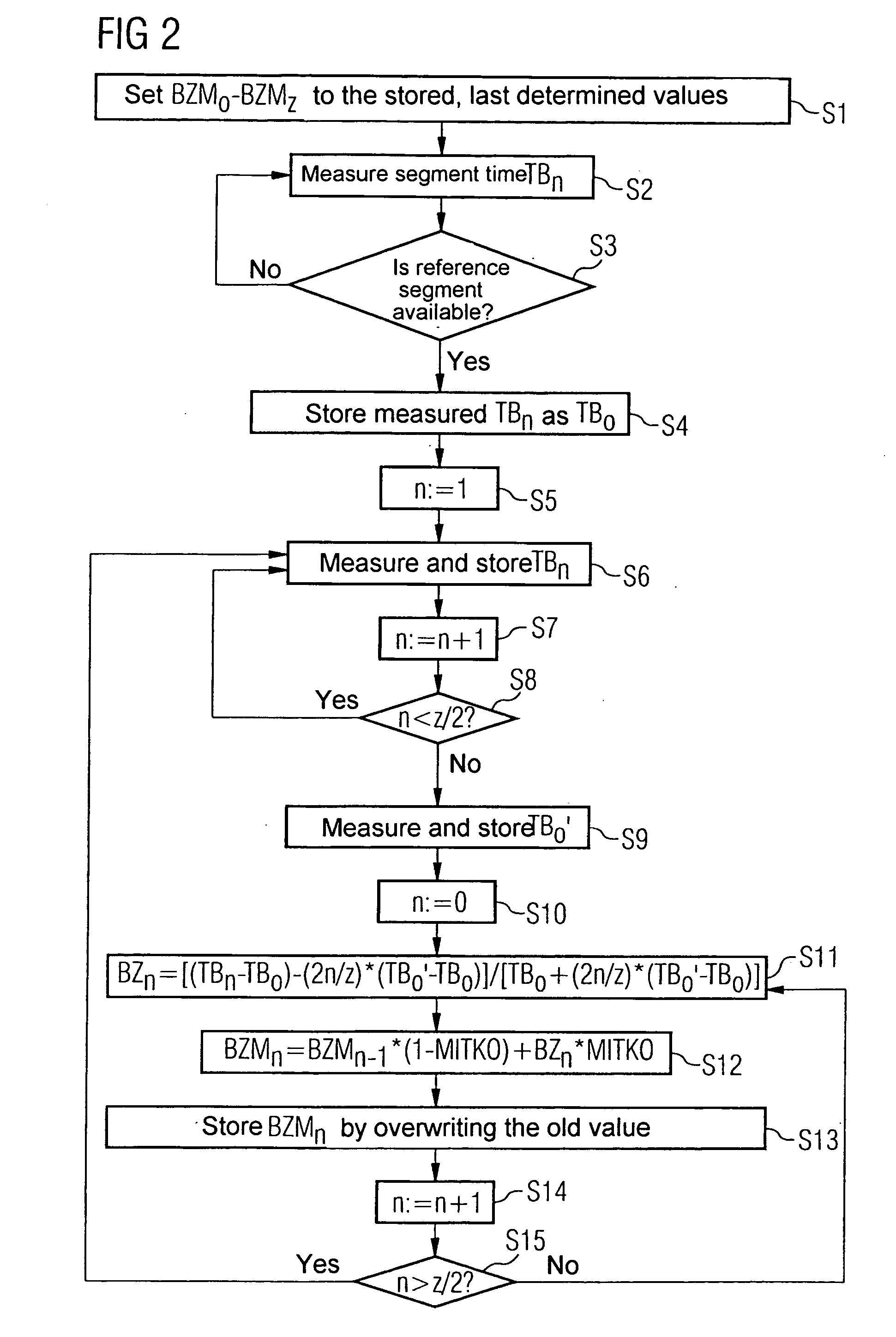
FIG. 2 shows the inventive method, correction values being determined with this embodiment for individual segments. Steps S1 to S7 correspond to the steps S1 to S7 described in FIG. 1, the averaged correction values in this embodiment being designated BZM0 to BZMz and the measured segment times TBn. In this embodiment, the number of segments on the crankshaft or on the tachometer disk is restricted to half the number of cylinders of the internal combustion engine, that is, to z / 2. The flow therefore branches from step S8 to step S9 if the condition n<z / 2 is not met. In step S9, the segment time of the reference segment is again measured and stored as TB0′. In contrast to the embodiment described in FIG. 1, the new measurement of the segment time of the reference segment occurs after just one crankshaft rotation. In the subsequent steps S10 to S15, the correction values BZn or the averaged correction values BZMn are calculated and stored. To this end, in step S10 the counter is ...


PUM


Abstract

A method and device for determining a correction value for a measured segment time, which a shaft of an internal combustion engine, in particular a crankshaft, needs in order to rotate about a defined angular range, evaluate the following relationship in order to determine correction values for individual cylinders:
AZn=[(TGn−TG0)−(n/z)*(TG0′−TG0)]/[TG0+(n/z)*(TG0′−TG0)],
where z is the number of cylinders of the internal combustion engine, n is the number of the cylinder currently under consideration,
  • TGn is the measured segment time of the cylinder with the number n,
  • TG0 is the measured segment time of a reference segment of a reference cylinder,
  • TG0′ is the segment time of the reference segment of the reference cylinder measured two crankshaft rotations after the segment time TG0, and
  • AZn is a correction value for the segment time of the cylinder with the number n.

Description

TECHNICAL FIELD OF THE INVENTION The invention relates to methods and devices for determining a correction value for a measured segment time, which a shaft of an internal combustion engine, in particular a crankshaft, needs in order to rotate about a defined angular range. DESCRIPTION OF THE RELATED ART Measurement of the segment time is effected in that the shaft itself or a tachometer disk connected to it have markings which are scanned by sensors. The sensor system can for example comprise an inductive sensor or a Hall-effect sensor and a segment wheel. The time which the shaft needs in order to rotate about a certain angle of rotation is measured. In general, the rotational speed of the shaft can be measured by this means. It is, however, also possible, to record fluctuations in the rotational speed, the accuracy of resolution depending on the interval between the markings on the circumference of the shaft or of the tachometer disk, that is, on the segment size. Such measureme...

Claims


Application Information

Patent Timeline
IPC IPC(8): F02D41/34G01M15/06G01M15/11G01P3/489
CPCF02D41/0097G01P3/489G01M15/11G01M15/06
Inventor BRUNS, CARSTEN
Owner VITESCO TECH GMBH
Why Eureka
Try Eureka