Terminal structure of superconducting cable and superconducting cable line therewith

a technology of superconducting cables and terminal structures, which is applied in the direction of superconductor devices, connection contact materials, cables, etc., can solve the problems of mechanical strength, heat applied to melt solder, and inability to achieve compression molding as employed for normal conducting cables, so as to reduce the magnetic field leaking from each cable core, the effect of increasing the connection resistan

Inactive Publication Date: 2005-03-24
SUMITOMO ELECTRIC IND LTD +1
View PDF0 Cites 17 Cited by
  • Summary
  • Abstract
  • Description
  • Claims
  • Application Information

AI Technical Summary

Benefits of technology

[0013] In accordance with the present invention a superconducting cable has a superconducting layer having a radially outer portion provided with a conductive connection member (a connection electrode) fixed to the superconducting layer by employing a low melting solder to prevent an electrical insulation layer from having impaired insulating property associated with attaching the connection member. The connection electrode can have a ground wire previously attached thereto, and the electrode with the wire can be attached to the superconducting layer, the superconducting shield layer, in particular, to eliminate the necessity of directly attaching the ground wire to the superconducting shield layer. This can prevent the superconducting shield layer from damage associated with attaching the ground wire and also prevent the electrical insulation layer from having impaired insulating property.
[0031] Thus, as has been described above, in the present superconducting cable's terminal structure a cable core can have a superconducting layer having a radially outer portion provided with a connection electrode having a ground wire attached thereto to effectively prevent the superconducting layer from damage associated with attaching the ground wire and prevent an electrical insulation layer from impaired insulating property. Furthermore, for multiphase cables, connection electrodes can be linked together to short circuit superconducting shield layers. As such, each cable core's superconducting shield layer can create a magnetic field canceling a magnetic field generated from each superconductor layer, and a large magnetic field generated external to each cable core can be prevented. In particular, in the present invention, the superconducting layer and the connection electrode can be connected with low-melting solder, and attaching the connection electrode does not impair the electrical insulation layer's insulating property.

Problems solved by technology

If the superconducting cable has the superconducting shield layer grounded in the manner employed to ground a normal conducting cable's shield layer, however, a problem arises: First, a superconducting layer is formed of a superconducting wire which does not have a mechanical strength that can endure compression bonding.
As such, such compression molding as employed for normal conducting cables cannot be employed.
If the superconducting cable has the superconducting shield layer with a ground wire attached thereto by using the above-described, typical solder, which has a melting point higher than the temperature limit of the electrical insulation layer underlying the superconducting shield layer, the heat applied to melt the solder impairs the electrical insulation layer's insulating property.
Furthermore, directly attaching a ground wire to the superconducting shield layer of the superconducting cable may damage a superconducting wire configuring the superconducting shield layer and impair the electrically insulation layer's insulating property, as described above.

Method used


Image

  • Terminal structure of superconducting cable and superconducting cable line therewith
  • Terminal structure of superconducting cable and superconducting cable line therewith
  • Terminal structure of superconducting cable and superconducting cable line therewith

Examples


Embodiment Construction

[0038] Hereinafter the present invention in embodiment will be described.

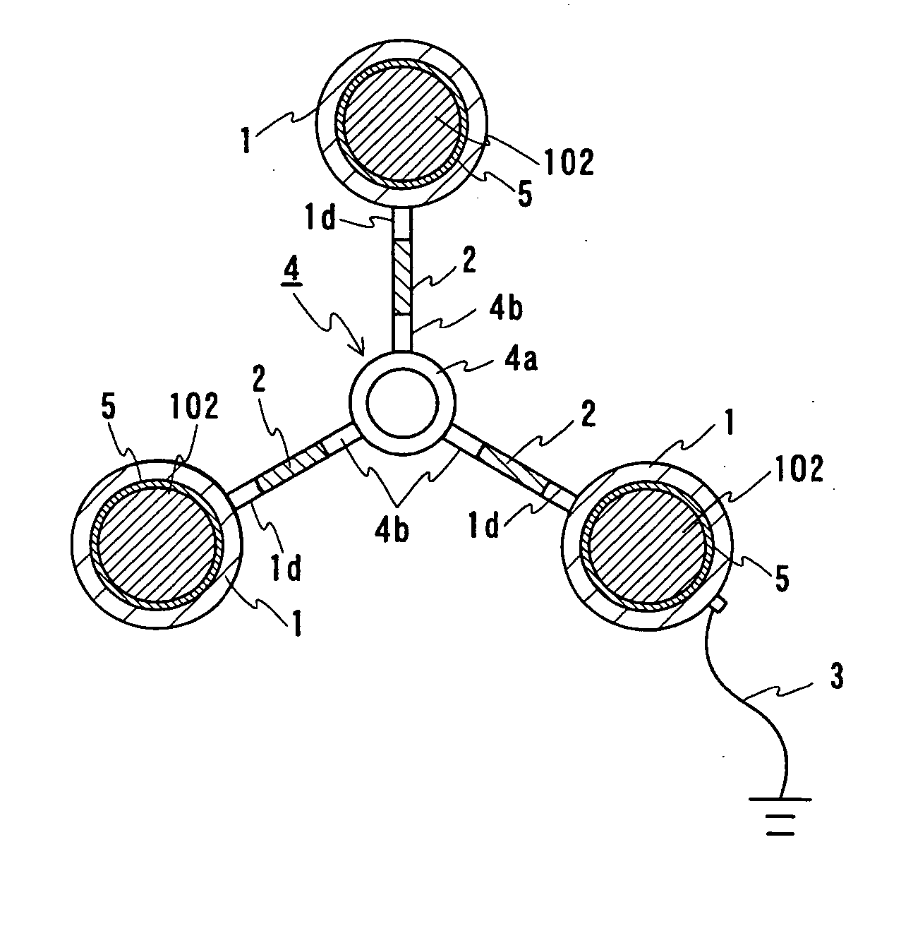
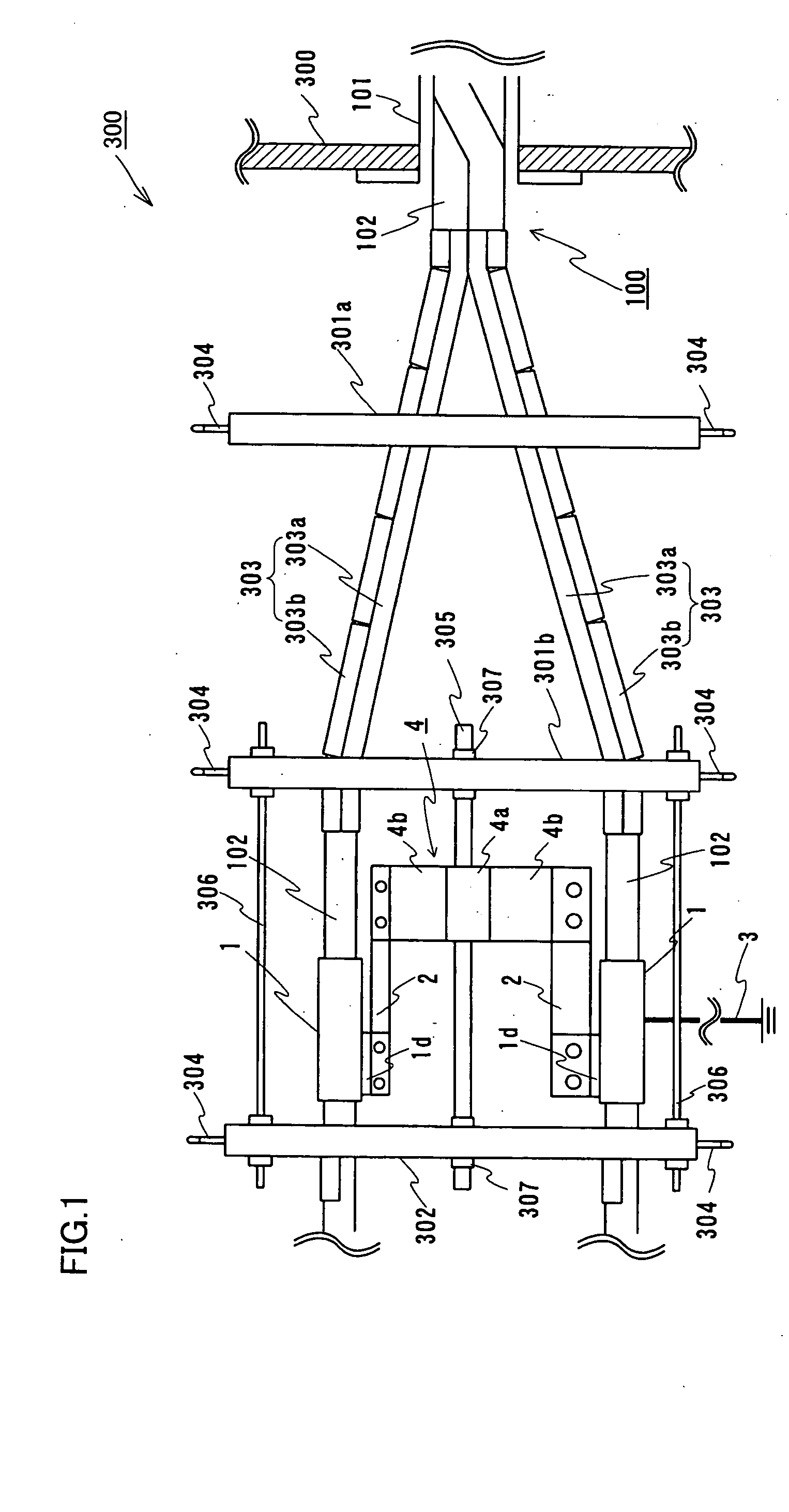
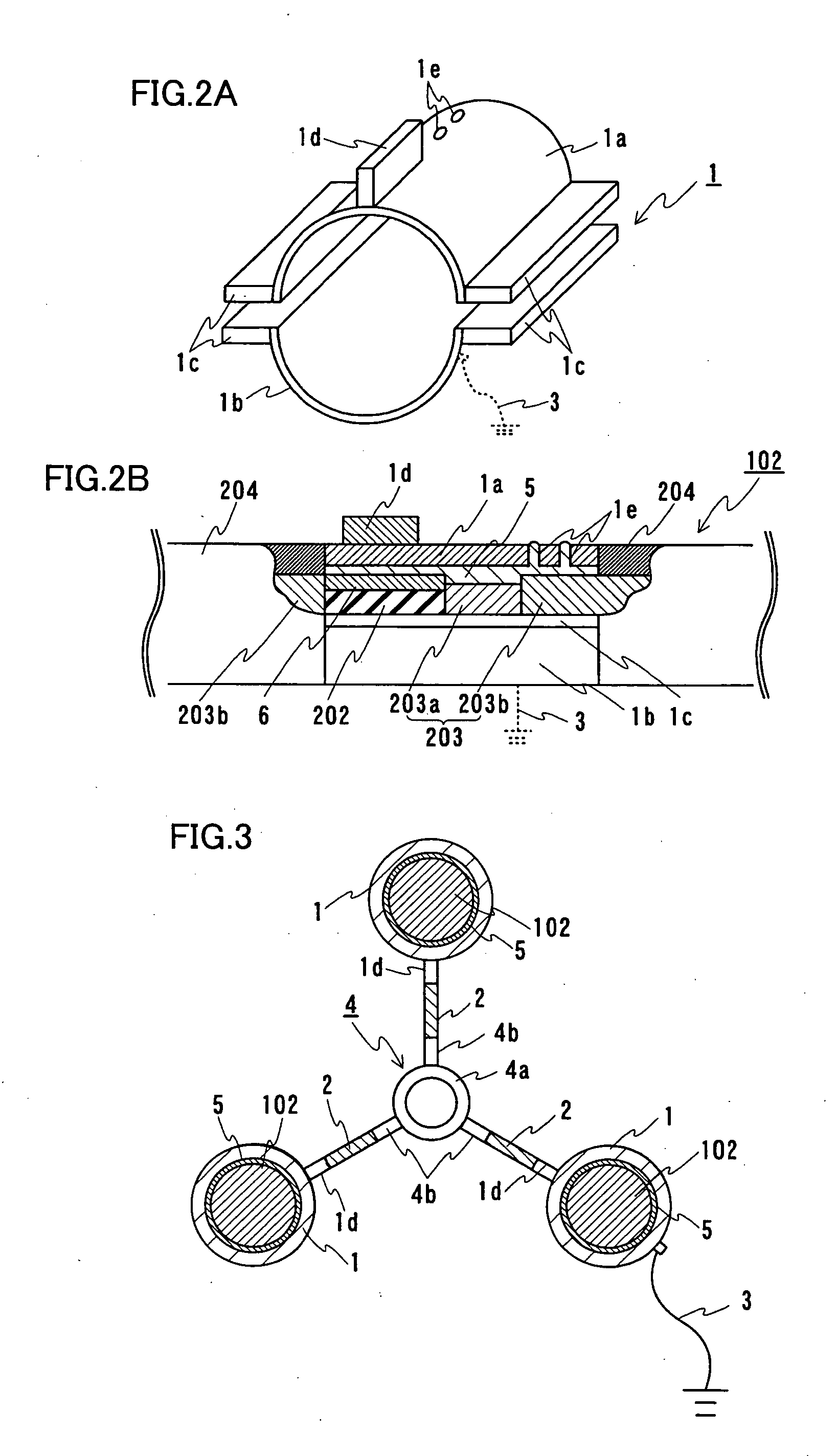
[0039]FIG. 1 shows a superconducting cable line 300 including a terminal structure of a superconducting cable 100. The superconducting cable 100 terminal structure is a terminal structure of a multiphase superconducting cable including a plurality of cable cores 102 having a superconducting layer and an electrical insulation layer, and each cable core 102 has the superconducting layer (in the present embodiment, a superconducting shield layer) surrounded by a connection electrode 1. The superconducting shield layer and connection electrode 1 are connected with a low-melting solder. In the present embodiment 3-phase superconducting cable 100 including three cable cores 102 will be used as an example for description.

[0040] The present embodiment employs 3-phase superconducting cable 100, which is similar in configuration to that shown in FIG. 5. More specifically, as seen radially outwards, cable core 102 inclu...


PUM

PropertyMeasurementUnit
melting pointaaaaaaaaaa

Abstract

The present invention provides a terminal structure of a superconducting cable including a cable core having a superconducting shield layer and an electrical insulation layer. The superconducting shield layer has a radially outer portion provided with by a connection electrode and the superconducting shield layer and the connection electrode are connected together with a low melting solder. The connection electrode has a ground wire connected thereto to ground the superconducting shield layer. For a multiphase cable including a plurality of cable cores, connection electrodes are linked by a conductive coupling member to short circuit superconducting shield layers. The superconducting shield layer can be grounded without impaired insulating property of the electrical insulation layer.

Description

BACKGROUND OF THE INVENTION [0001] 1. Field of the Invention [0002] The present invention relates generally to terminal structures of superconducting cables including a cable core having a superconducting layer, and superconducting cable lines including the terminal structure, and particularly to terminal structures of superconducting cables helping to attach a ground wire to the superconducting layer while preventing an electrical insulation layer from having impaired insulating property, and lines including the terminal structure. [0003] 2. Description of the Background Art [0004] As one of superconducting cables that have been produced using a superconductor layer formed of a Bi-based high-temperature superconducting tape for example, not only a single phase cable including a single cable core but a multiphase superconducting cable of multicore type that is produced by assembling a plurality of cable cores into one unit is also under development. [0005] Referring to FIG. 5, this ...

Claims


Application Information

Patent Timeline
Patent Type & Authority Applications(United States)
IPC IPC(8): H01R4/64H01B12/00H01B12/02H01R4/02H01R4/68H02G1/14H02G15/076
CPCH01R4/68Y10S505/887Y02E40/648H02G15/34Y02E40/60H01B12/00H01B12/02
Inventor YUMURA, HIROYASUTAKAHASHI, YOSHIHISAMATSUO, KIMIYOSHIHONJO, SHOICHIMIMURA, TOMOO
Owner SUMITOMO ELECTRIC IND LTD
Why Eureka
Try Eureka