Method for pressurized mud cap and reverse circulation drilling from a floating drilling rig using a sealed marine riser

a technology of seals and risers, which is applied in the direction of sealing/packing, drilling pipes, and drilling holes/well accessories. it can solve the problems of significant rig downtime, environmental problems, and the possibility of over-reaching the seal pressure rating of these joints

Active Publication Date: 2005-03-24
WEATHERFORD TECH HLDG LLC
View PDF99 Cites 113 Cited by
  • Summary
  • Abstract
  • Description
  • Claims
  • Application Information

AI Technical Summary

Benefits of technology

[0015] A method for pressurized mud cap and reverse circulation drilling is disclosed for use with a floating rig or structure. A seal housing having a rotatable seal is connected to the top of a marine riser fixed to the floor of the ocean. The seal housing includes a first housing opening sized to pump drilling fluid down the annulus of the riser. In the mud cap drilling embodiment, the drilling fluid forms a mud cap at a downhole location of the riser. In the reverse circulation drilling embodiment, the drilling fluid flows down the riser and returns up the rotatable tubular to the floating structure. The seal rotating with the rotatable tubular allows the riser and seal housing to maintain a predetermined pressure in the drilling fluid that is desirable in both of those drilling embodiments. A flexible conduit or hose is used to compensate for the relative movement between the seal housing and the floating structure since the floating structure moves independent of the seal housing.

Problems solved by technology

If the joints need replacement, significant rig downtime can be expected.
In addition, the seal pressure rating for these joints may be exceeded by emerging and existing drilling techniques that require surface pressure in the riser mud return system, such as in underbalanced operations comprising drilling, completions and workovers, gas-liquid mud systems and pressurized mud handling systems.
Both the open bell-nipple and seals in the slip and ball joints create environmental issues of potential leaks of fluid.
A mud cap can typically be used to control bottomhole pressure on a trip and to keep gas or liquid from coming to the surface in a well, resulting in total lost circulation.
While a theft zone, when drilling conventionally, can cause undesirable excessive or total lost circulation, differentially stuck pipe, and resulting well control issues, mud cap drilling takes advantage of the presence of a theft zone.
This mud cap drilling technique is well known for onshore wells and offshore fixed wells, but has been unavailable for offshore floating rigs because of the inability to handle the vertical and horizontal movements of the floating rig structure relative to the annulus, while sealing the top of the riser.
Although PMCD has been used in onshore drilling, PMCD has been unavailable for use offshore on floating rigs, such as semi-submersible rigs.

Method used


Image

  • Method for pressurized mud cap and reverse circulation drilling from a floating drilling rig using a sealed marine riser
  • Method for pressurized mud cap and reverse circulation drilling from a floating drilling rig using a sealed marine riser
  • Method for pressurized mud cap and reverse circulation drilling from a floating drilling rig using a sealed marine riser

Examples


Embodiment Construction

[0033]FIG. 14 discloses the preferred embodiment of the present invention.

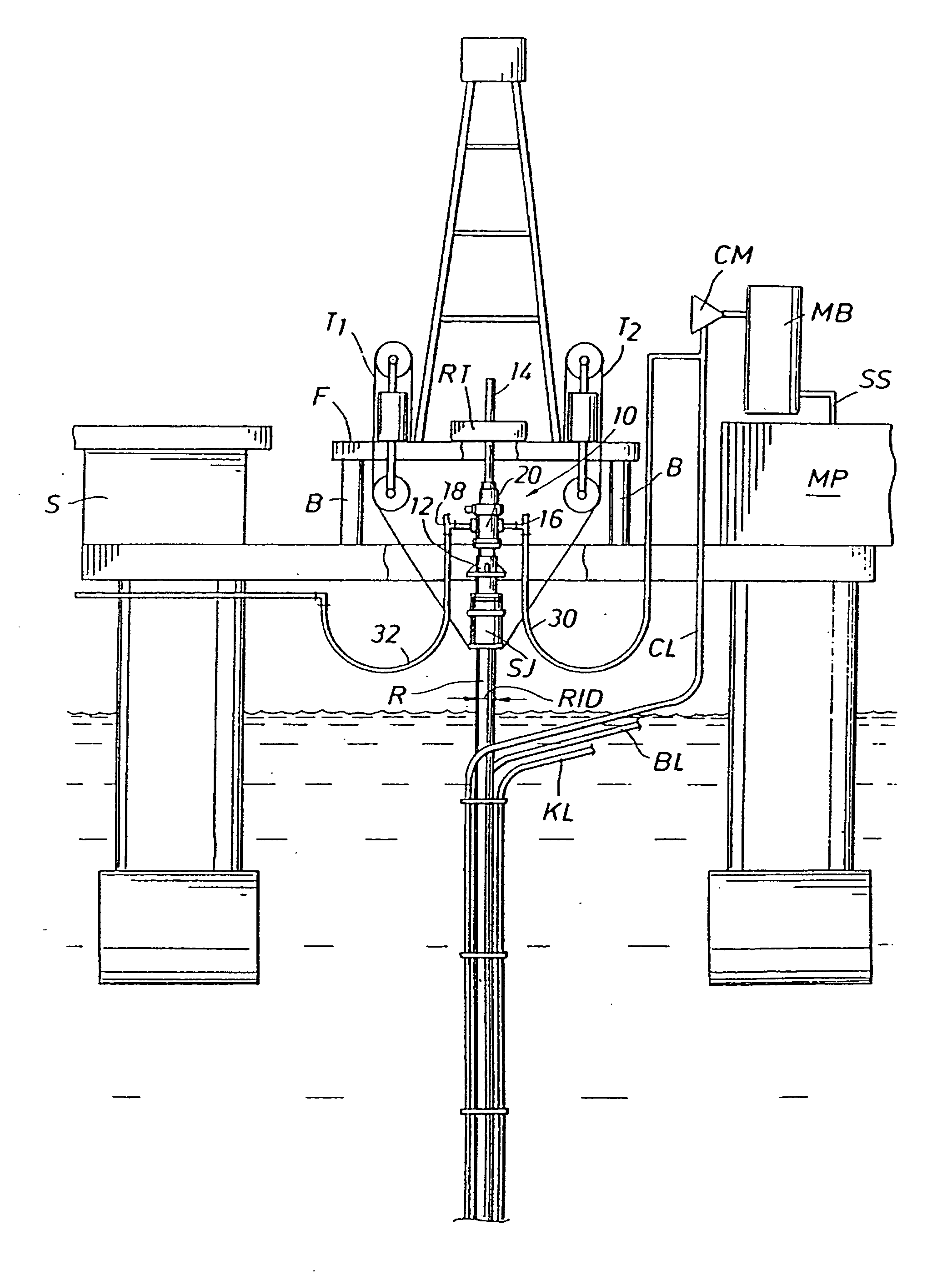
[0034]FIG. 2 illustrates a rotating control head (RCH), generally designated as 10, of the present invention. The RCH 10 is similar, except for modifications discussed below, to the RCH disclosed in U.S. Pat. No. 5,662,181, entitled “Rotating Blowout Preventer” and assigned to the assignee of the present invention, Weatherford / Lamb, Inc. of Houston, Tex. The '181 patent, incorporated herein by reference for all purposes, discloses a product now available from the assignee that is designated Model 7100. The modified RCH 10 can be attached above the riser R, when the slip joint SJ is locked into place, such as shown in the embodiment of FIG. 2, so that there is no relative vertical movement between the inner barrel IB and outer barrel DB of the slip joint SJ. It is contemplated that the slip joint SJ can be removed from the riser R and the RCH 10 attached directly to the riser R. In either embodiment of a locke...


PUM


Abstract

A method for drilling in the floor of an ocean from a floating structure using a rotatable tubular includes a seal housing having a rotatable seal connected above a portion of a marine riser fixed to the floor of the ocean. The seal rotating with the rotating tubular allows the riser and seal housing to maintain a predetermined pressure in the system that is desirable in pressurized mud cap and reverse circulation drilling. A flexible conduit or hose is used to compensate for relative movement of the seal housing and the floating structure because the floating structure moves independent of the seal housing. The drilling fluid is pumped from the floating structure into an annulus of the riser, allowing the formation of a mud cap downhole in the riser, or allowing reverse circulation of the drilling fluid down the riser, returning up the rotatable tubular to the floating structure.

Description

BACKGROUND OF THE INVENTION [0001] 1. Field of the Invention [0002] The present invention relates to a method for pressurized mud cap and reverse circulation drilling from a floating structure using a sealed marine riser while drilling. In particular, the present invention relates to a method for pressurized mud cap and reverse circulation drilling from a floating structure while drilling in the floor of an ocean using a rotating control head. [0003] 2. Description of the Related Art [0004] Marine risers extending from a wellhead fixed on the floor of an ocean have been used to circulate drilling fluid back to a floating structure or rig. The riser must be large enough in internal diameter to accommodate the largest bit and pipe that will be used in drilling a borehole into the floor of the ocean. Conventional risers now have internal diameters of approximately 20 inches, though other diameters are and can be used. [0005] An example of a marine riser and some of the associated drill...

Claims


Application Information

Patent Timeline
Patent Type & Authority Applications(United States)
IPC IPC(8): E21B19/00E21B21/08
CPCE21B21/08E21B19/004E21B19/006E21B7/12E21B33/08E21B7/128E21B19/002E21B33/085
Inventor HANNEGAN, DON M.
Owner WEATHERFORD TECH HLDG LLC
Why Eureka
Try Eureka