Waveguide based light source

a waveguide and light source technology, applied in the field of light sources, can solve the problems of extreme brightness, and achieve the effects of high power excitation and emission, small cross section, and high brightness

Inactive Publication Date: 2005-03-24
QUANTUM VISION
View PDF11 Cites 36 Cited by
  • Summary
  • Abstract
  • Description
  • Claims
  • Application Information

AI Technical Summary

Benefits of technology

[0009] An embodiment of the present invention consists of a relatively large area of phosphor film excited through, by way of example only, conventional broad area means. The device may be many square centimeters in extent allowing for high power excitation and emission. The embodiment is formed such that a substantial amount of the light emitted by the phosphor is confined to one or more guided modes with a very small cross section. These guided modes exit the device through one or more regions of similarly small cross section resulting in extremely high brightness.

Problems solved by technology

These guided modes exit the device through one or more regions of similarly small cross section resulting in extremely high brightness.

Method used


Image

  • Waveguide based light source
  • Waveguide based light source
  • Waveguide based light source

Examples


Embodiment Construction

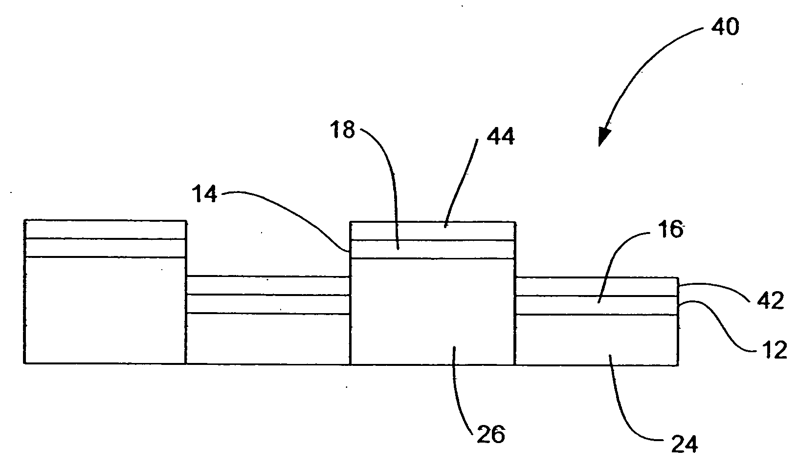
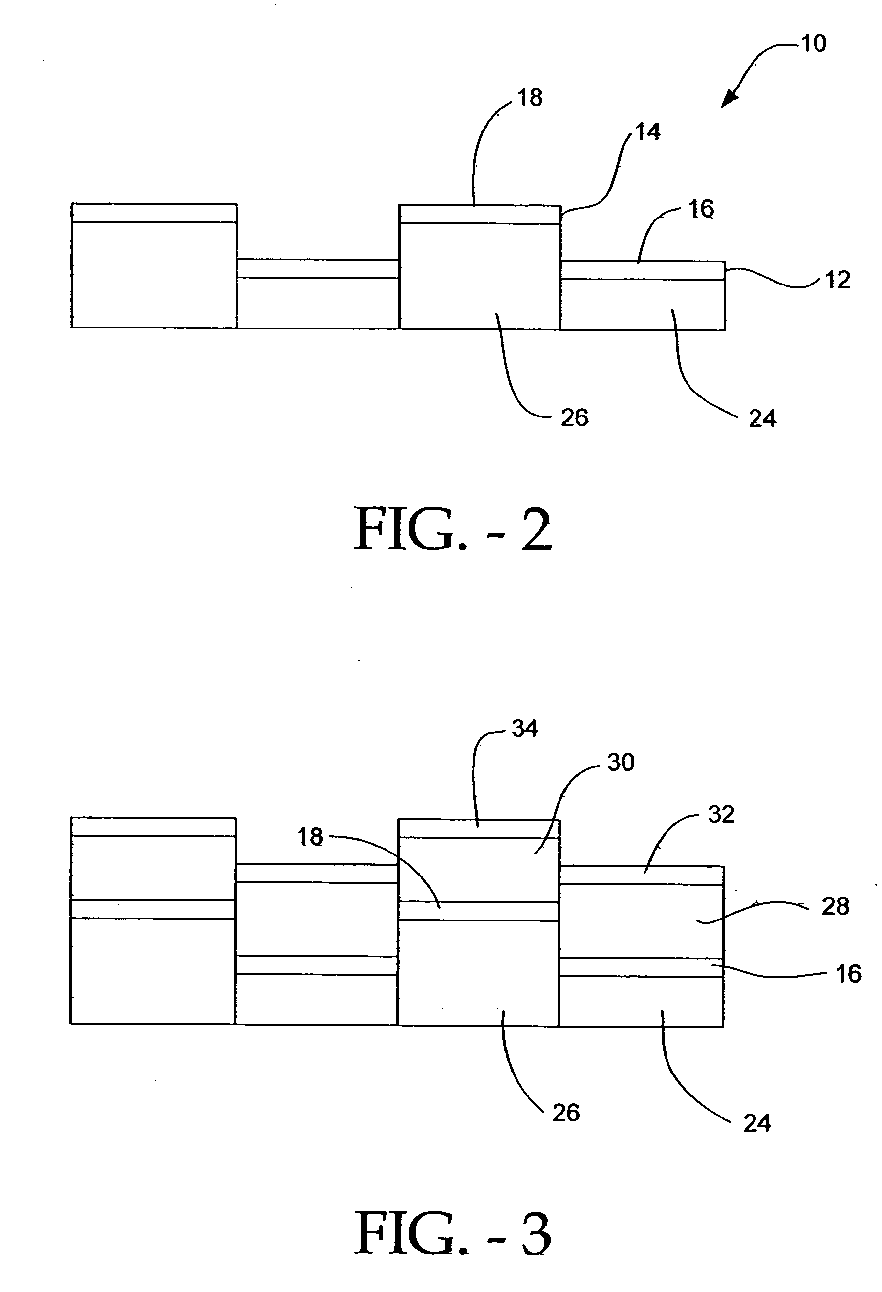
[0016] In the preferred embodiment the construction of the device is such that the guided modes have two dimensions which are of the order of a wavelength of light. One of these dimensions is given by the thickness 12, 14 of the thin film layer 16, 18 involved. This small dimension or thickness 12 can be formed by in-plane patterning.

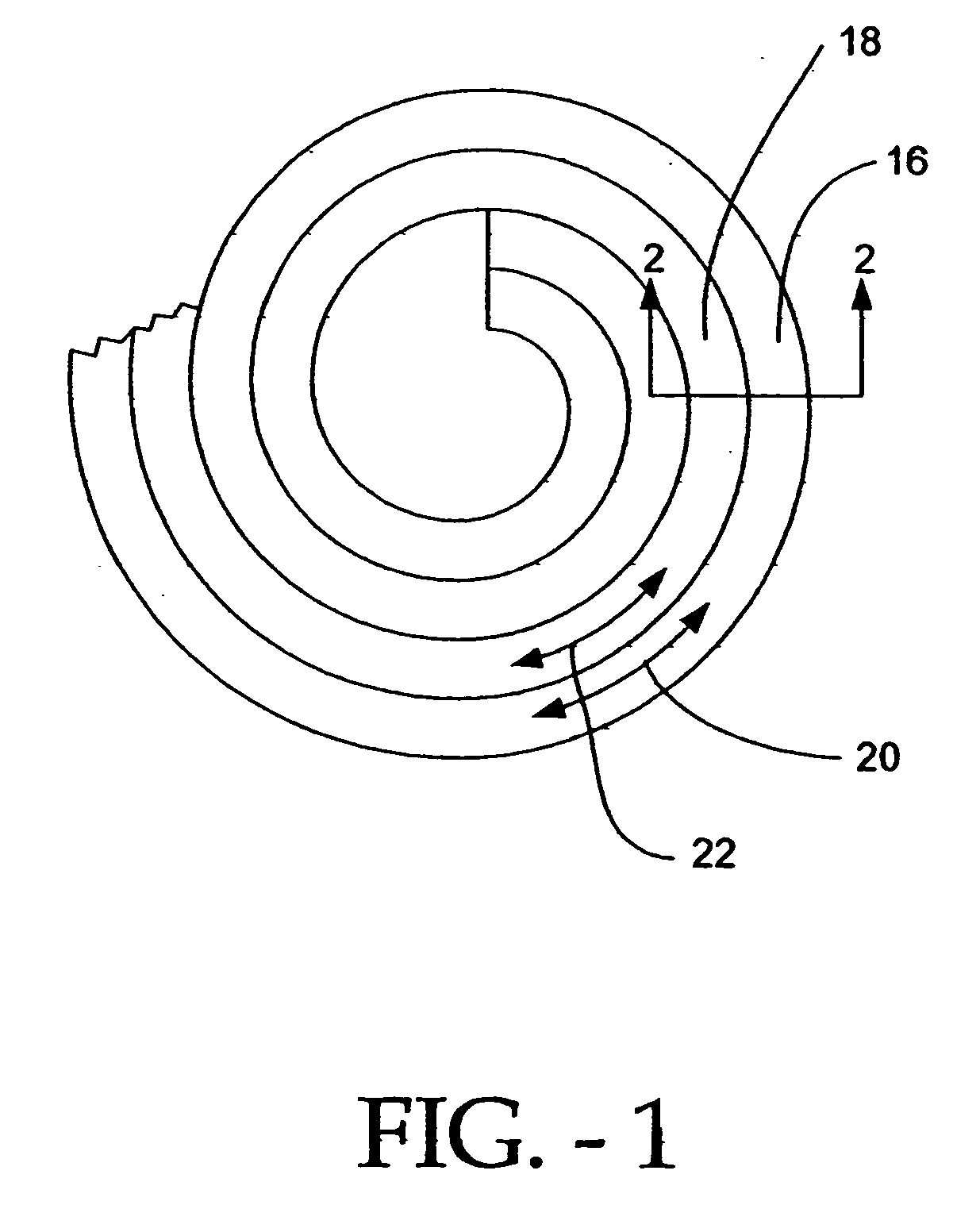
[0017] The other in-plane dimension 20, 22 is sufficiently long in extent to produce a total area which may be many square centimeters. This one long dimension 20, 22 may consist of spirals or parallel lines so that a circular, rectangle, or other simple shape or surface area is substantially filled allowing for efficient broad area excitation.

[0018] The emitted light travels along the spirals or parallel lines and exits the device through “openings” approximately the same size as the small dimensions 12, 18 of the waveguide. FIG. 1 illustrates this spiral waveguide and is similar in appearance to a coiled garden hose.

[0019] In the simplest embodimen...


PUM


Abstract

A wave guide based light source having a phosphor film with a large two-dimensional extent and a small thickness. The phosphor film is excited by an excitation means.

Description

[0001] This application is a continuation application of U.S. application Ser. No. 09 / 855,254, filed May 15, 2001, now U.S. patent application Publication No. 2003 / 0044160, Published Mar. 6, 2003 (QVIS-01057US1), which claims priority to Provisional Patent Application, S / C No. 60 / 204,645 filed May 17, 2000 (QVIS-01057US0).FIELD OF THE INVENTION [0002] The present invention relates to a light source comprising a phosphor film and a method of concentrating the emitted light. BACKGROUND OF THE INVENTION [0003] High brightness light sources are needed for many applications including optical fiber illumination and image projection. In optical fiber illumination, particularly for telecommunications applications, light-emitting diodes (LEDs), and semiconductor diode lasers are the dominant light sources as described in the article of Hecht, which is attached hereto and incorporated herein by reference (see Hecht, Jeff, Back to Basics: Fiber-optic Light Sources, Laser Focus World, January 2...

Claims


Application Information

Patent Timeline
Patent Type & Authority Applications(United States)
IPC IPC(8): F21V8/00F21V7/04G02B6/00H01J63/06H01LH05B33/00
CPCH01J63/06G02B6/0003
Inventor JONES, MICHIEAL L.JAFFE, STEVEN M.OLMSTED, BRIAN L.
Owner QUANTUM VISION
Why Eureka
Try Eureka