Low particulate matter emission fabric filter

Inactive Publication Date: 2020-03-12
GENERAL ELECTRIC TECH GMBH
View PDF0 Cites 2 Cited by
  • Summary
  • Abstract
  • Description
  • Claims
  • Application Information

AI Technical Summary

Benefits of technology

[0006]In view of the above, disclosed herein is a relatively low particulate matter emission fabric filter system. Also, disclosed herein is a method of using the subject relatively low particulate matter emission fabric filter system for effective particulate matter collection, including during the period of time from filter bag cleaning up until dust cake formation on the surfaces of the filter bags. For purposes of this disclosure, “dust cake formation” is defined herein as a complete, non-sporadic, coating of a surface of a filter bag with particulate matter. As such, the subject fabric filter system comprises a gas flow damper system arranged at an inlet of each fabric filter chamber and/or at an outlet of each fabric filter chamber to control gas flow velocity through each fabric filter chamber during the period from filter bag cleaning up until dust cake formation on the surfaces of the filter bags. Filter bags without exterior surface dust cake formation filtering at a relatively lower gas velocity have unex

Problems solved by technology

Following such cleaning of the filter bags, filter bags with no exterior surface dust cakes are relatively less effective in trapping or collecting particulate matter than are identical filter bags with exterior surface

Method used


Image

  • Low particulate matter emission fabric filter

Examples


Embodiment Construction

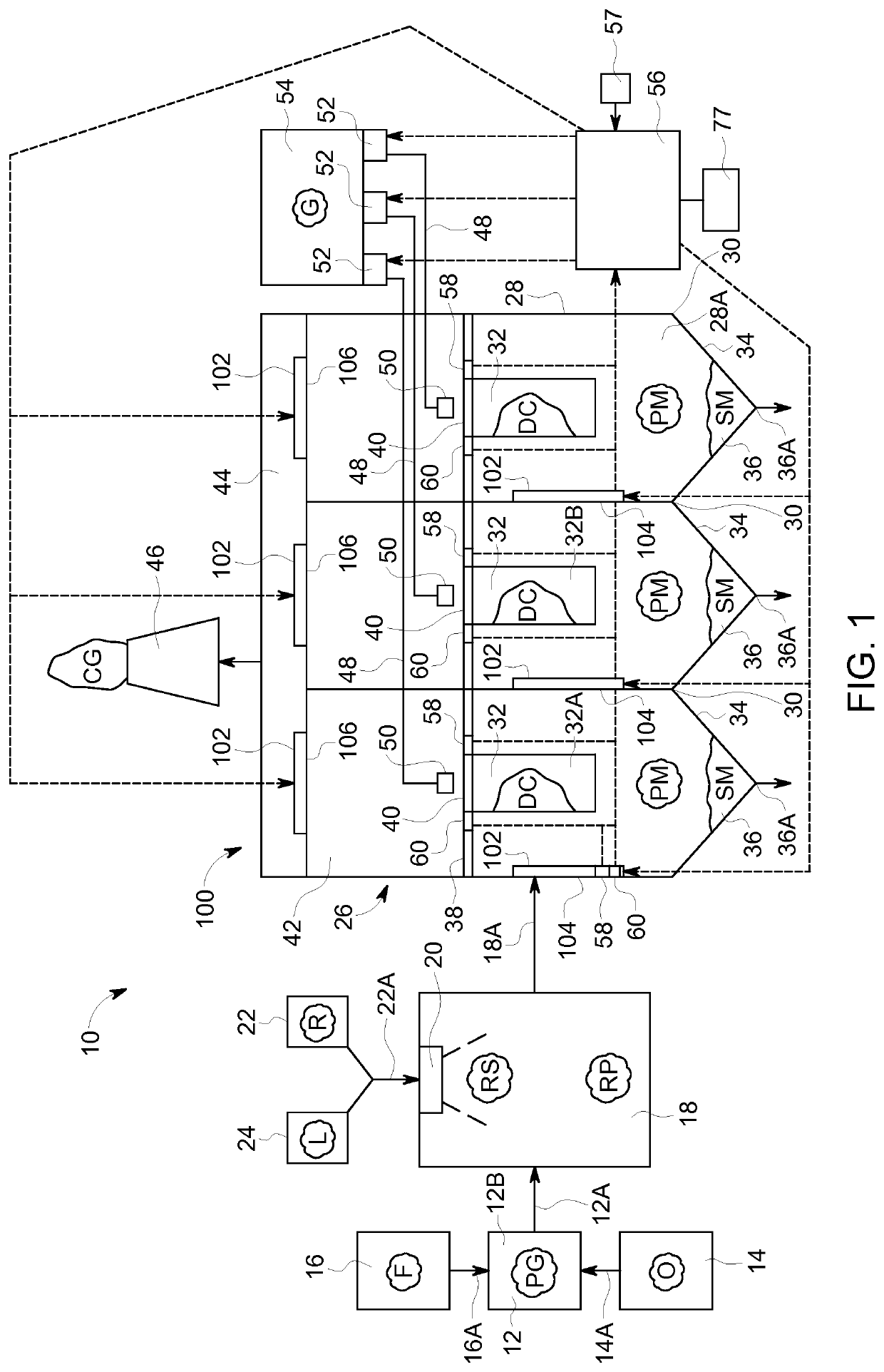
[0013]Referring to FIG. 1, disclosed herein is a plant 10 such as a power plant or an industrial plant that when in operation generates a polluted gas PG. An example of such a plant 10 for purposes of illustration not limitation, is a power plant that includes a combustion unit 12, such as a steam producing boiler unit, that when in operation generates the polluted gas PG. The combustion unit 12 may be supplied at least one oxygen containing gas O, e.g., air, O2 gas, or gases that include O2 gas, from a gas supply 14 via a fluidly connected supply pipe 14A. Likewise, the combustion unit 12 is supplied a carbonaceous fuel F from a fuel supply 16 via a fluidly connected fuel duct 16A for combustion of the fuel F in the presence of the supplied at least one oxygen containing gas O within the combustion unit 12. The fuel F supplied to combustion unit 12 is preferably a fossil fuel such as for example coal, oil, or natural gas. In addition to steam, polluted gas PG is produced upon fuel ...


PUM

PropertyMeasurementUnit
Speedaaaaaaaaaa
Speedaaaaaaaaaa
Speedaaaaaaaaaa

Abstract

A fabric filter system (26) useful for filtering a polluted gas to achieve a cleaned gas with a relatively low particulate matter content, including during a period of time from fabric filter bag (32) cleaning up until dust cake formation on the fabric filter bag (32). For such purpose, the subject fabric filter system (26) is equipped with a polluted gas flow damper system (100) to control polluted gas velocity through the fabric filter system (26), particularly for a relatively reduced polluted gas velocity during the period of time from fabric filter bag (32) cleaning up until dust cake formation on the fabric filter bag (32).

Description

FIELD OF THE DISCLOSURE[0001]In general, the present disclosure relates to a fabric filter system useful for filtering a polluted gas to achieve a filtered gas with a relatively low particulate matter content. More specifically, the present disclosure relates to a fabric filter system useful for filtering a polluted gas to achieve a filtered gas with a relatively low particulate matter content, including during the period of time from filter bag cleaning up until dust cake formation on the surface of the filter bag.BACKGROUND OF THE DISCLOSURE[0002]Commercial “bag house” type filter installations typically consist of a plurality of parallel filter units. Each such filter unit contains a plurality of parallel rows of vertically arranged filter elements in the form of filter bags. Each such filter bag has a top end opening. A gas polluted with particulate matter is channeled through the filter bags to filter and collect particulate matter entrained in the gas. Hence, upon filtration a...

Claims


Application Information

Patent Timeline
IPC IPC(8): B01D46/02B01D46/00B01D46/44B01D46/42
CPCB01D46/448B01D46/0068B01D46/446B01D46/023B01D46/4272B01D46/02B01D46/46B01D46/71B01D46/04B01D46/72
Inventor NILSSON, PETER LARS
Owner GENERAL ELECTRIC TECH GMBH
Why Eureka
Try Eureka