Wavelength selectable light source

a light source and selectable technology, applied in the direction of semiconductor laser arrangement, optical resonator shape and construction, semiconductor lasers, etc., can solve the problems of large flat mirror, large optical aberration, large flat mirror, etc., and achieve high power emission and reliability

Inactive Publication Date: 2005-12-27
RGT UNIV OF CALIFORNIA
View PDF22 Cites 7 Cited by
  • Summary
  • Abstract
  • Description
  • Claims
  • Application Information

AI Technical Summary

Benefits of technology

[0022]The use of an external optical pump also provides an advantage over some other types of tunable VCSELs, because the pump laser can be separately optimized for high power emission and reliability, and its excess heat can be located remotely from the 2-D array of VCSELs.
[0023]The use of the second movable mirror separate from the 2-D array of VCSELs is also an advantage, because it allows for separate optimizations of VCSEL and mirror performance, because the second movable mirror is not part of the optical cavity of the VCSEL. This is not the case with other types of devices having only a single VCSEL that uses movable mirrors.

Problems solved by technology

This poses technical problems that could include difficulties, such as fabricating a large flat movable mirror, slow response time of the large mirror, aberrations in the optics, and astigmatism in the lens.
These difficulties affect the usefulness of this technique when larger array dimensions are considered.
Even technologies that can use multiple device active regions for gain at different wavelengths, such as linear cascade and multiplexed in-plane lasers, are limited in their wavelength range due to difficulties in scaling to a high number of devices and in coupling the power from all the devices efficiently into a single fiber.

Method used


Image

  • Wavelength selectable light source
  • Wavelength selectable light source
  • Wavelength selectable light source

Examples


Embodiment Construction

[0028]In the following description, reference is made to the accompanying drawings which form a part hereof, and which is shown, by way of illustration, an embodiment of the present invention. It is understood that other embodiments may be utilized and structural changes may be made without departing from the scope of the present invention.

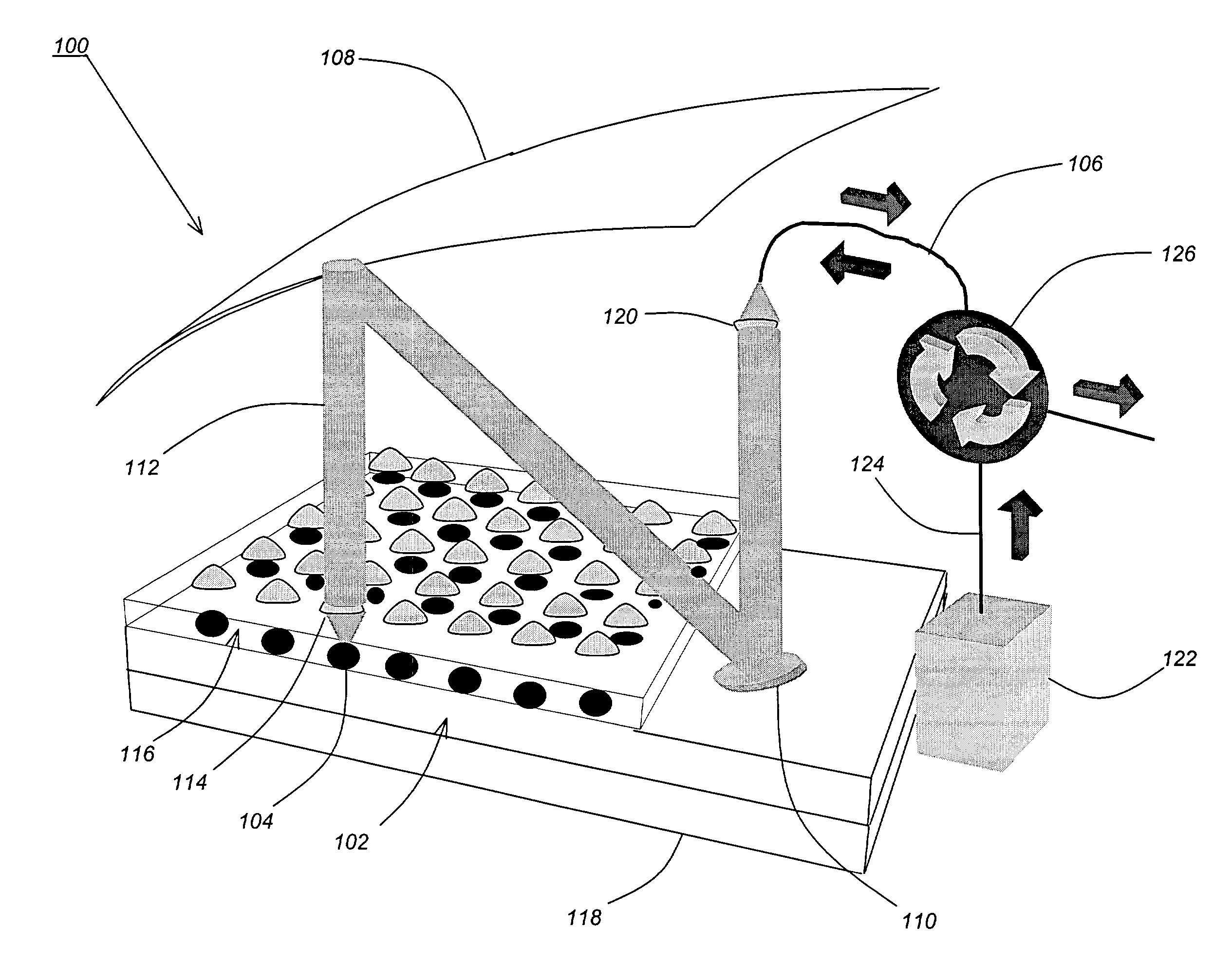
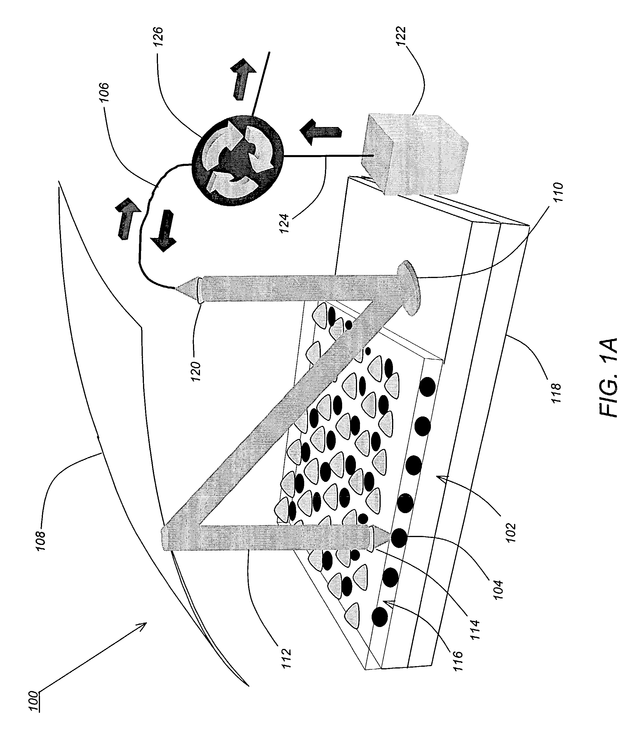
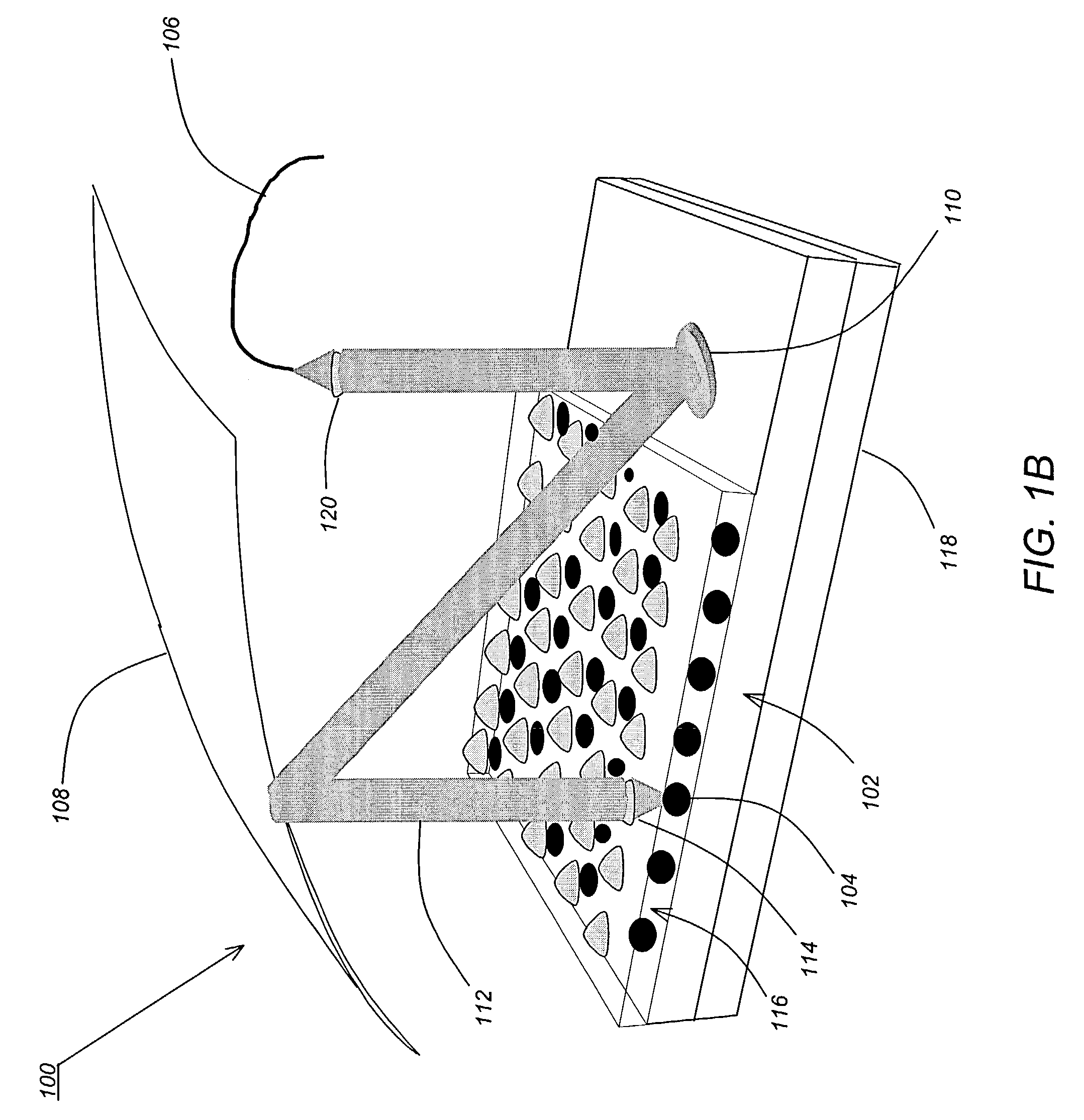
[0029]FIGS. 1A and 1B illustrate wavelength selectable light sources according to alternative embodiments of the present invention. FIG. 1A illustrates a first embodiment where the wavelength selectable light source uses optical pumping, and FIG. 1B illustrates a second embodiment where the wavelength selectable light source is implemented without optical pumping.

[0030]As shown in FIGS. 1A and 1B, a wavelength selectable light source 100 of the present invention can be realized using a two-dimensional (2-D) array of variable wavelength light emitters, which in this embodiment comprise vertical-cavity surface-emitting lasers (VCSELs) 102 fabricated...


PUM


Abstract

A wavelength selectable light source is comprised of a two-dimensional (2-D) array of variable wavelength vertical-cavity surface-emitting lasers (VCSELs), wherein light beams emitted from the VCSELs are coupled into an output optical fiber. The light beams emitted from the VCSELs are collimated via a 2-D array of micro-lenses, the collimated light beams impinge upon a first fixed-position mirror that points each of the collimated light beams toward a second movable mirror located at a common focal point in a common area, and the second movable mirror redirects the collimated light beams into a lens coupled to the output optical fiber. By moving the second movable mirror, different ones of the collimated light beams can be directed into the output optical fiber, so that the second movable mirror performs a wavelength selection function.

Description

CROSS-REFERENCE TO RELATED APPLICATION[0001]This application claims priority under 35 U.S.C. §119(e) to co-pending and commonly-assigned Provisional Application Ser. No. 60 / 383,510, entitled “VERTICAL-CAVITY TUNABLE LASER,” filed on May 28, 2002, by Jonathan Charles Geske, which application is incorporated by reference herein.STATEMENT OF GOVERNMENT SUPPORT[0002]This invention was made with Government support by the Air Force of Scientific Research (AFOSR) Grant F49620-96-1-0349. The government may have certain rights in this invention.BACKGROUND OF THE INVENTION[0003]1. Field of the Invention[0004]This invention relates to optical devices, and more particularly, to wavelength selectable light sources and tunable lasers.[0005]2. Description of the Related Art[0006]Wavelength selectable light sources and tunable lasers are well known in the art. Wavelength selectable light sources are often used in place of a tunable laser, or in conjunction with laser tuning. Tunable lasers function...

Claims


Application Information

Patent Timeline
Patent Type & Authority Patents(United States)
IPC IPC(8): H01S5/00H01S5/022H01S5/0687H01S5/40H01S5/42
CPCH01S5/423H01S5/02284H01S5/02292H01S5/0687H01S5/4012H01S5/4087H01S5/02255H01S5/02251
Inventor GESKE, JONATHAN CHARLES
Owner RGT UNIV OF CALIFORNIA
Why Eureka
Try Eureka